1890
No-Till Air Drill
- Floating hitch on 1890 No-Till Air Drill
- Parallel Tracking™ or AutoTrac™ compatibility
- Convenient dual-row spacing hydraulics
- Optional air seeder row markers
Features
Confidence in rates from row to row with RelativeFlow™ Blockage sensing
With the RelativeFlow blockage sensing, operators can see the flow rate of both seed and fertilizer from inside the tractor cab. Sensors on all primary towers and secondary hoses monitor the relative product flow, giving you a better view of the flow rate of both seed and fertilizer from the cart to the opener from inside your tractor cab. This exclusive technology can help you identify any problems before potential blockage occurs.
RelativeFlow Blockage is available on the following models:
- P540 - 12.2-m (40-ft)
- P556 - 17.1-m (56-ft)
- P576 - 23.2-m (76-ft)
- N500C - all widths
- 1890 - 15.2-m (50-ft) and 18.3-m (60-ft)
- N530F - 9.1-m (30-ft)
- N540F - 12.2-m (40-ft)
- N543F - 13.1-m (43-ft)
- N560F - 18.3-m (60-ft)
RelativeFlow Blockage is compatible with hydraulic drive carts for model year 2014 and newer 1910, model year 2013 and newer 550 Carts, C650 and C850 Air Cart.
Below are the GreenStar™ 3 2630 Display screens for the blockage monitoring system. For complete details and information, see the owner’s manual.
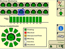 Blockage monitoring screen on GreenStar™ 3 2630
 The RelativeFlow sensing chart shows the amount of flow through each sensor on the selected tower. Sensitivity for the blockage system can be adjusted if desired, as shown below.
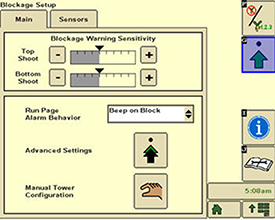 Blockage monitoring screen on GreenStar 3 2630
 Blockage warning sensitivity allows the producer to set and change the sensitivity of the sensors to meet their preferences. Increasing the sensitivity means the system is more likely to show a false blockage, while less sensitivity means the system is more likely to miss a blockage.
Multiple run-page alarm behavior options are available for selection.
 Blockage monitoring screen on GreenStar 3 2630
 Below are the Gen 4 display screens for the blockage monitoring system on the N500C.
For complete details and information reference, the owner’s manual.
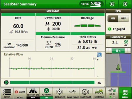 RelativeFlow Blockage configured run page
 The SeedStar™ system run page displays the five major run settings. Clicking on any of the tiles will take an operator to that specific page (shown below).
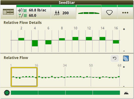 Operators can zoom into flow details by meter section when selecting blockage tiles
 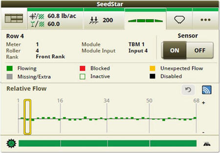 Operators can zoom into the row level to access row/sensor information and turn a sensor on/off independently
 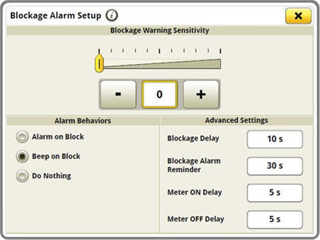 Blockage sensitivities and alarm delays are all set up on one easy-to-navigate screen
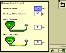
 Blockage alarm delays can be set up by clicking on the advanced settings button from the blockage set-up screen.
- A blockage delay is how long a blockage should occur before an alarm is sounded.
- The blockage alarm reminder is how often the alarm should sound when a blockage occurs.
- The meter on delay is the time from when the meter is turned on until the blockage sensor should start monitoring for blockage.
- The meter off delay is the time from when the meter is turned off until the blockage sensor should start monitoring to verify no flow.
For more detailed information, see the owner’s manual.
Air tools with Relative Flow Blockage are not compatible with 1910 air carts with ground drive.
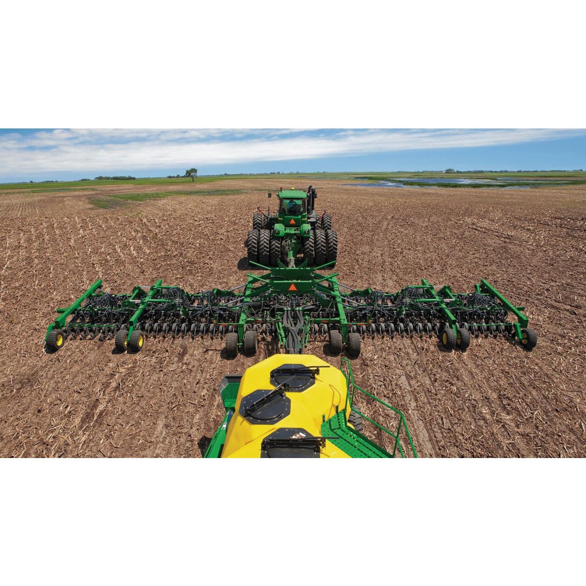
1890 working widths
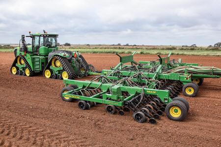
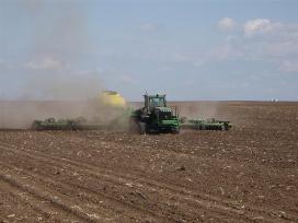 18.30-m (60-ft) 1890 seeding into sunflower stalks
 John Deere offers six working widths in the 1890 air drill.
Working widths, row spacings:
- 9.15 m (30 ft) on 190-mm (7.5-in.)/380-mm (15-in.) or 254-mm (10-in.) row spacing
- 11 m (36 ft) on 190-mm (7.5-in.)/380-mm (15-in.) or 254-mm (10-in.) row spacing
- 12.20 m (40 ft) on 190-mm (7.5-in.)/380-mm (15-in.) or 254-mm (10-in.) row spacing
- 12.95 m (42.5 ft) on 190-mm (7.5-in.)/380-mm (15-in.) or 254-mm (10-in.) row spacing
- 15.25 m (50 ft) on 190-mm (7.5-in.)/380-mm (15-in.) or 254-mm (10-in.) row spacing
- 18.30 m (60 ft) on 190-mm (7.5-in.)/380-mm (15-in.) or 254-mm (10-in.) row spacing
NOTE: Recommended tractors are 279.6 kW (375 hp) for the 15.25-m (50-ft) model and 335.5 kW (450 hp) for the 18.30-m (60-ft) model.
Weight brackets allow for additional ballast
 Weights at rear of mainframe
 ![Wing weight bracket (shown on 18.30-m [60-ft] 1890)](https://salesmanual.deere.com/sales/salesmanual/images/AU/en/seeding/features_attachment/1890drill/wing_weightbracket1890.jpg) Wing weight bracket (shown on 18.30-m [60-ft] 1890)
Wing weight bracket (shown on 18.30-m [60-ft] 1890) Additional weights may be required when seeding in dry, hard soils or in extremely high rates of residue. These weights may be removed when seeding in mellow or loose soils. A rear weight bracket and a weight bracket on the front corner of each wing are in base equipment on the 9.15-m, 11-m, 12.20-m, and 12.95-m (30-ft, 36-ft, 40-ft, and 42-ft) 1890s.
The brackets allow the addition of R127764 tractor suitcase weights to provide increased down pressure. A total of 14 tractor suitcase weights can be added at the rear of the mainframe. Six tractor suitcase weights can be added on each outer wing.
NOTE: Due to the heavier mainframe on the 15.25-m and 18.30-m (50-ft and 60-ft) 1890s, mainframe weights and weight brackets are not in base equipment or required. There is an option to order kit AA76487 from service parts for the wing weight brackets.
NOTE: Order code 6505 (open-center valve kit) is not available for the 15.25-m and 18.30-m (50-ft and 60-ft) models.
IMPORTANT: Wing weights and row markers are not compatible and should not be used together.
Parallel Tracking system or AutoTrac™ assisted steering compatibility
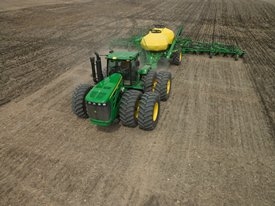 Seeding with John Deere AutoTrac with SF2 signal
 John Deere air seeding equipment is compatible with Parallel Tracking or AutoTrac.
These systems:
- Are compatible with SeedStar™ 2 system
- Add value by assisting in minimizing costly skips or overlap
- Are cost-effective and weigh less when compared to mechanical row markers
1890 mainframe and wings features
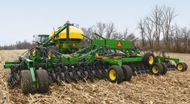 1890 Seeding on 380-mm (15-in.) rows with rear rank
 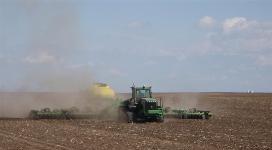 1890 18.30-m (60-ft) five-section on (7.5-in.) spacing
 The 1890 features a three-section or five-section (15.25-m [50-ft] and 18.30-m [60-ft] models) drawn flexible frame with a convenient overcenter fold for transport or storage.
NOTE: Recommended tractor is 279.6 kW (375 hp) for the 15.25-m (50-ft) model and 335.5 kW (450 hp) for the 18.30-m (60-ft) model.
Productivity of the 15.25-m (50-ft) and 18.30-m (60-ft) widths compared to the 12.95-m (42.5-ft) model:
- The 15.25-m (50-ft) model is 17 percent more productive per pass
- The 18.30-m (60-ft) model is 42 percent more productive per pass
Features on all six models:
- Two ranks of ProSeries™ Openers
- 1.35 m (52.7 in.) between ranks of openers
- 380-mm (15-in.) clearance between openers on 190-mm (7.5-in.) spacing machine
- 508-mm (20-in.) clearance between openers on 254-mm (10-in.) spacing machine
- 100-mm x 150-mm (4-in. x 6-in.) cross tubes and 50-mm x 150-mm (2-in. x 6-in.) end tubes
- 560 mm (22 in.) of underframe clearance
- Wings flex 20 degree up and 10 degree down
- 108-degree overcenter fold
The two-rank frame design provides excellent residue flow and field performance.
Spoked gauge wheels
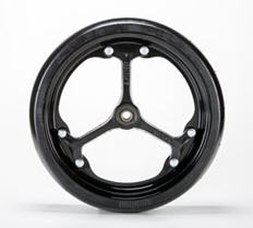 Spoked gauge wheels
 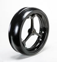 Spoked gauge wheel
 Growers have historically had to make some difficult planting and seeding decisions due to weather. Operators have been forced to plant in wet conditions that are far from optimal in order to plant within the optimum planting window. Those operators have experienced poor performance from wet soils working in between the depth gauge wheel and the opener disk and not having a way out. This creates the possibility of the depth gauge wheel or opener disk to seize up and drag through the soil.
The spoke gauge wheel is a solution for operators who plant in these conditions to allow the mud and debris that get caught behind the depth gauge wheel to easily flow through the wheel and continue providing superior depth performance.
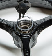
The spoke gauge wheel is designed for optimum performance. Its features include serviceable, stamped inner and outer rims. The wheel also has cast spokes and bearing hubs for increased strength. This allows smaller spokes, creating larger open surface area for mud and debris to flow more easily than competitor’s wheels. Another improvement over the closed gauge wheel is a snap-ring bearing retention. Simply remove the snap ring, replace the bearing, and place the snap ring back.
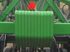
 Gauge wheel
 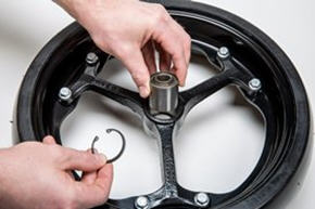 Gauge wheel
 Heavy trash fields from no-till environments have also tested very well with the new spoke gauge wheel. Some growers provided feedback of crop residue getting inside and jamming up the gauge wheel and opener. This spoke gauge wheel has shown exceptional performance within these areas as well. These wheels are compatible with both 90 Series openers on seeding tools and planter row-units.
Below is a chart that demonstrates a competitive advantage over MudSmith™ wheels for mud and residue flow:
| MudSmith | John Deere | Percent improvement | |
| Open area | 329 cm2 (51 cu in.) | 471 cm2 (73 cu in.) | 43 percent |
| Rim height | 1.9 cm (3/4 in.) | 1.4 cm (9/16 in.) | 25 percent |
| Spoke width | 3.5 cm (1-3/8 in.) | 1.9 cm (3/4 in.) | 45 percent |
The wheel is serviceable along with other parts.
- AA86055 – complete wheel assembly
- A101570 – inner wheel rim half
- A101571 – outer wheel rim half
Not compatible in dual gauge wheel applications.
MudSmith is a trademark of MudSmith, LLC.
ProSeries™ Openers provide excellent penetration
 ProSeries Openers
 ProSeries Openers are in base equipment on all 1890 and N500F Separate Fertilizer Placement (SFP), 1990 Central Commodity System (CCS™), and 1590 Air Drills.
On the 1890 models, the single-disk openers are on 190-mm (7.5-in.) or 254-mm (10-in.) row spacing. On 15.25-m (50-ft) and 18.3-m (60-ft) 1890 models, the 190-mm/380-mm (7.5-in./15-in.) or 254-mm/508-mm (10-in./20-in.) dual-row spacing feature is in base equipment. The single-disk openers provide consistent and accurate seed placement.
The ProSeries Openers are gang mounted and are hydraulically raised and lowered. The hydraulic downforce system also offers a wide range of downforce settings for the openers.
 Active hydraulic downforce pressure valve
 The active hydraulics:
- Work in conjunction with the opener spring
- Provide an adjustable range of 75 kg (165 lb) to 180 kg (400 lb) of down pressure per opener
- Benefit: penetrate hard soils and heavy residue
- The cylinders allow the openers to travel up or down an additional 405 mm (16 in.) with active hydraulic down pressure to follow the ground
- Provide the openers additional pressure when needed or allow the openers to go into relief if the pressure becomes too high
The down pressure:
- Is easily adjusted with the pressure valve located on the front of the mainframe
- Provides the operator the ability to quickly adjust, or dial in, the down pressure as operating conditions change
NOTE: For additional ballast in hard-to-penetrate conditions, tractor suitcase weights may also be added to the mainframe and wings to obtain maximum down pressure per opener.
The ProSeries Openers:
- Work not only in no-till conditions, but also in minimum or reduced-till conditions
- Provide 51 mm (2 in.) of free travel in the opener before spring down pressure takes over
- Benefit: allows the opener to move over uneven ground conditions and minimize the chance of the gauge wheels bulldozing soil in soft or mellow conditions
- The opener spring travels a maximum of 203-mm (8-in.) up or 150-mm (6-in.) down before the hydraulics react to uneven seedbeds