1910
Air Commodity Cart
- Choice of auger or conveyor
- Stationary single-shoot manifold
- In-line drive system transfers power efficiently
- Up to 430 bu. grain tank capacity on tow-between models
Features
The Total Seeding Solution – Experience the John Deere Advantage
John Deere has the seeding solutions that go above expectations with a complete line of everything needed in small grains. Offering a variety of openers for your chosen practice in a variety of configurations and sizes. All with integrated technology throughout the seeding train allows for effortless setup and seamless documentation.
 Total seeding solution
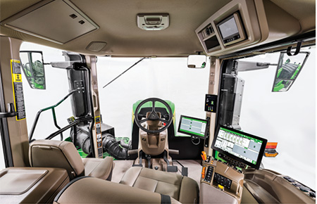
 Setting up a John Deere seeding train is quick and easy with the plug and play technology. All data and technology operate through the Gen 4 display and ultimately up to John Deere Operation Center™ that can be viewed from anywhere at any time. Not only does the complete John Deere seeding solution all operate through one display but it eliminates the difficulty and time-consuming tasks of setting up extra displays and harnesses.
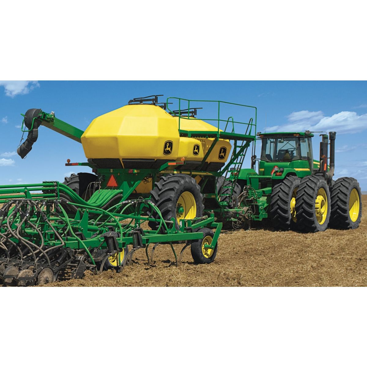
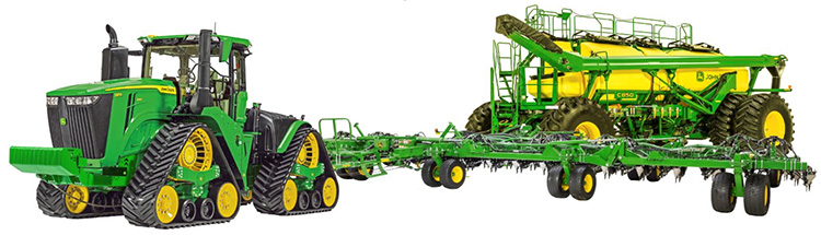
 John Deere tractor paired with John Deere tool and cart
 With a complete John Deere seeding solution, there are multiple different onboard and offboard technologies shown below that improve the overall seeding production step. Many of these technologies are exclusive to John Deere. Each of these technologies bring different customer value that overall lead to the ultimate John Deere seeding solution!
On the go, quick adjust downforce with TruSet™ from the cab
- Adjust downforce pressure to improve uniform emergence
- Set presets to quickly adjust from field to field
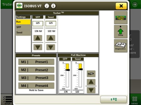 TruSet downforce display
 Monitor blockage row by row from the cab with RelativeFlow™
- Seed with confidence while monitoring each row
- Detect blockage early and know exactly where it is
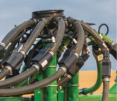 RelativeFlow blockage sensors
 ActiveCal™ display
- Calibrate the meters from the cab utilizing the tank scales
- Improved confidence the correct seeding rates are being met
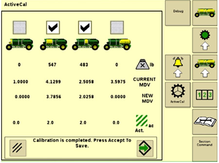 ActiveCal display
 SectionCommand™ controls seed and fertilizer output
- Controls seed and fertilizer output by closing and opening gates on the meters
- Minimize skips and overlaps leading to reduced inputs
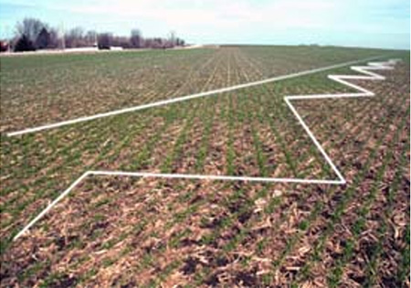 Example of seeded field with SectionCommand
 AutoTrac™ Implement Guidance and AutoTrac Turn Automation
- Make every operator an experienced operator
- Precisely placed implements for more accurate seeding, less operator fatigue, and more productivity
- Hands-free turns within field headlands (with AutoTrac Turn Automation enabled)
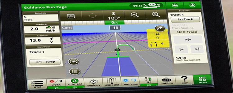 AutoTrac Turn Automation display
 John Deere Operation Center™
- Setup and manage your farm operations: equipment, team, fields, and crop inputs
- Plan work in advance to increase job quality and efficiency with Work Planner
- Map based prescriptions can be used with variable rates
- Analyze this season’s results to improve next season’s crops
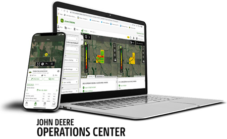 John Deere Operation Center web and mobile
 Operation Center Mobile
- View your data on the go; remotely monitor job quality, productivity, machine performance, and quickly make informed decisions
- Manage and monitor from anywhere at any time with near real-time field and machine updates
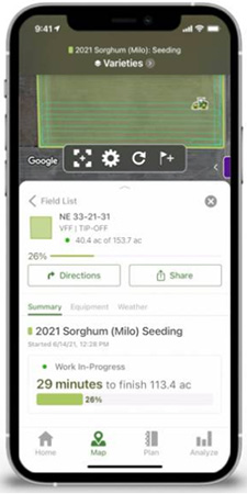 Operation Center Mobile
 Connected Support
- Expert Alerts proactively notifies your dealer of any issues
- Remote display access allows for easy on the go support
 Connected Support
 For more information regarding Large Tractors and Precision Ag, view the following landing pages
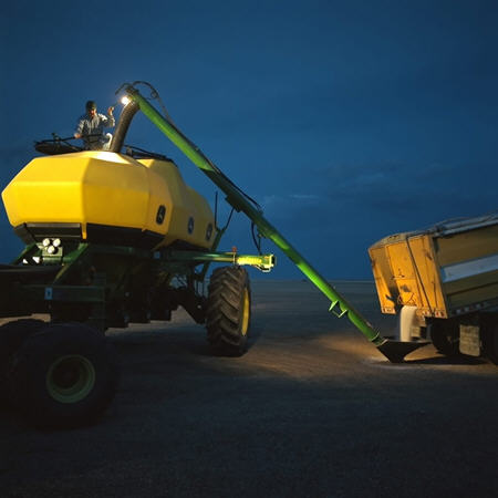
Choice of auger or conveyor
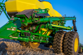 254-mm (10-in.) auger on 15,200-L (430-bu) cart
 As growers look for ways to increase efficiencies, one solution is to shorten the time required to fill. By increasing pit stop productivity, growers are able to cover more ground per day.
Producers have the choice of an auger or conveyor to fit their needs.
The 254-mm (10-in.) auger:
- Available on the 12,300-L (350-bu), 15,200-L (430-bu), and 19,400-L (550-bu) carts
- Loading rate 1800-L (50-bu) per minute
- Balanced for safe, convenient movement between storage and filling positions
- Able to fit under the meters for tank cleanout
The 203-mm (8-in.) auger:
- Available on 8,800-L (250-bu), 9,500-L (270-bu), and 12,000-L (340-bu) carts
- 700-L (20-bu) per minute fill rate
 305-mm (12-in.) conveyor
 The 305-mm (12-in.) conveyor provides producers with a gentle conveyance system:
- 305-mm (12-in.) wide belt with risers spaced on 150-mm (6-in.)
- 1400-L (40-bu) per minute fill rate
- Can also transfer fertilizer
- Cleanout trap door at the bottom
- Optional on all 1910 carts
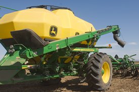
The telescoping spout provides the following benefits:
- Decreases fill time
- Easily fills each tank to the very top
- Improves movement when going from one tank to another, matching the tank height
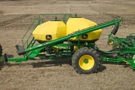
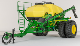
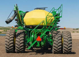
1910 cart configurations fit any farming operation
Growers around the world are always looking for ways to become more productive. The John Deere Seeding Group is continually looking for ways to help these growers increase productivity.
The 1910 Commodity Cart is one of the best ways to maximize productivity. By providing growers with several different tank configurations, the 1910 Cart allows growers to get the most benefit from input costs and time in the field.
The tanks are a semi-transparent, poly material. Owner benefits include:
- Corrosion resistance
- Ease of quickly viewing tank level from outside the cart
- Lightweight, increasing cart floatation
 Large-capacity, two-tank 1910
 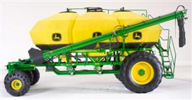 Three tanks increase productivity and efficiency
 Tow-behind capacity | |||||||
Two tanks | Total | ||||||
Bushel | 270 | 120 | 150 |
|
| ||
Litres | 9500 | 4200 | 5300 |
| |||
Tonnes | 7.2 | 3.2 | 4.0 |
| |||
Bushel | 350 | 150 | 200 |
|
| ||
Litres | 12,300 | 5300 | 7000 |
| |||
Tonnes | 9.4 | 4.0 | 5.4 |
| |||
Three tanks | Total | ||||||
Bushel | 340 | 120 | 70 | 150 |
| ||
Litres | 12,000 | 4200 | 2500 | 5300 | |||
Tonnes | 9.1 | 3.2 | 1.9 | 4.0 | |||
Bushel | 430 | 150 | 80 | 200 |
| ||
Litres | 15,200 | 5300 | 2800 | 7000 | |||
Tonnes | 11.5 | 4.0 | 2.1 | 5.4 | |||
Bushel | 550 | 200 | 150* | 200 |  | ||
Litres | 19,400 | 7000 | 5300 | 7000 | |||
Tonnes | 17.2 | 5.4 | 4.0 | 5.4 | |||
Tow-between capacity | |||||||
Two tanks | Total | ||||||
Bushel | 270 | 120 | 150 |
|
| ||
Litres | 9500 | 4200 | 5300 |
| |||
Tonnes | 7.2 | 3.2 | 4.0 |
| |||
Bushel | 350 | 150 | 200 |
|
| ||
Litres | 12,300 | 5300 | 7000 |
| |||
Tonnes | 9.4 | 4.0 | 5.4 |
| |||
Three tanks | Total | ||||||
Bushel | 430 | 150 | 80 | 200 |
| ||
Litres | 15,200 | 5300 | 2800 | 7000 | |||
Tonnes | 11.5 | 4.0 | 2.1 | 5.4 | |||


*Assumptions: cubic metre (1000 litres) of: wheat (front tank) = 0.76 tonnes, urea (middle tank) = 0.73 tonnes, fertilizer (rear tank) = 1.10 tonnes, bushel = 35.3 litres.
The tank lids are sealed, ensuring proper air pressure within the tank and at the meters. Sealing the tanks improves hydraulic fan utilization, providing efficient and optimum seeding accuracy.
With less than 0.13 bar (2 psi) of pressure in the tank, the pressure is equalized between the meters and tanks, providing an accurate, consistent seeding rate.
NOTE: Tank volume is measured to heaped capacity. When product is shoveled to the corners of the tank, the tanks may hold more than advertised capacity.
Meter seed accurately with confidence
A meter cartridge at each tank effectively meters seed or fertilizer into the primary manifold. Air carries the material to the secondary distributor for delivery to the openers on the seeding tool.
Meters are contained in a cartridge for convenient removal and are color coded for easy identification.
 Metering system
 A manual half-width disconnect is incorporated into the meter system:
- Allows one-half of the metering system to be manually shut off for irregular shaped headlands, point rows, etc. on mechanical drive carts.
- Allows the meter cartridge to be removed with material still in the tank(s).
- Allows tanks to be emptied with meter and primary manifold in place.
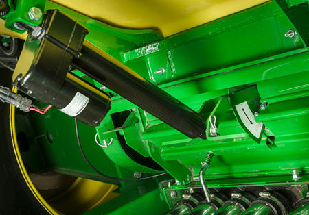 Electric actuator on C-Series Air Carts
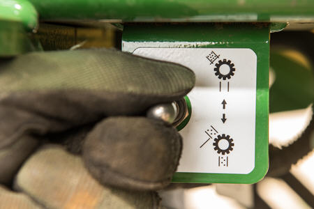
On the C-Series Air Carts, an electric actuator controls product flow from the tank to the meter housing:
- Allows complete shut off of product flow with little effort
- Allows the meter cartridge to be removed with material still in the tank(s)
- Allows tanks to be emptied with meter and primary manifold in place
Stairway and platform offer convenience and easy access
The easy-to-navigate staircase and large platform provide easy access to tank lids.
On tow-between carts, there is convenient front access to the platform, with step-over access when going from side-to-side over the front hitch.
 Tow-between cart, front access
 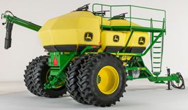 Tow-between cart, front access
 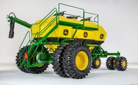 Tow-behind cart, rear access
 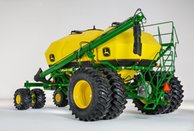 Tow-behind cart, rear access
 Efficient air system ensures consistent product delivery
Secondary manifolds
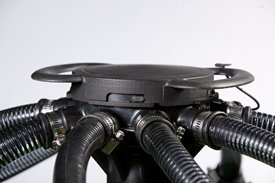 Secondary manifold on seeding tool
 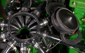 One-piece removable lid with tether
 Secondary manifolds with 25-mm (1-in.) diameter lines evenly distribute the seed and/or fertilizer from the primary manifold(s) to the furrow openers.
Primary hoses are color coded to conveniently connect the air distribution kit from the 1910 Cart to the seeding tool.
The 25-mm (1-in.) secondary lines used for seed are clear with a black spiral. For double-shoot air kits, hoses are clear with a green spiral.
The secondary manifold is made of durable, maintenance-free ethylene-propylene molded (EPDM) rubber. Features of the secondary manifold:
- Rust resistant, important when applying fertilizer or treated seed
- No tools required to remove lid
- No long bolt in the secondary tower
- Lid is tethered to the manifold
- The outlet ports are numbered
- Primary hoses are color coded to conveniently connect
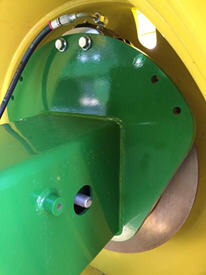
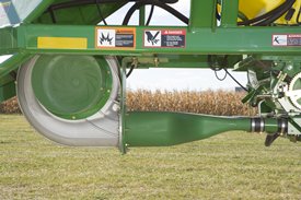 High-output, hydraulically driven fan
 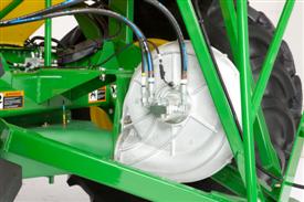 Fan as seen on 19,400-L (550-bu) cart
 The 1910 Commodity Air Cart uses an airstream to gently deliver seed and/or fertilizer to the openers. A strong, consistent airstream is necessary to keep product moving without plugging the air runs, while making sure damage is not occurring to the seed.
The large 450-mm (17.6-in.) diameter fan generates a low-velocity, high-volume airstream that carries the product to the openers. By using a high volume of air, there is less chance of damaging seed, while decreasing the likelihood of plugging the air system.
The fan is driven by the tractor's hydraulic system. It requires approximately 53- to 75-L/min (14 to 26-gpm) oil flow for operation.
IMPORTANT: The 53- to 75-L/min (14- to 26-gpm) is for the 1910 Cart fan only; additional hydraulic capacity from the tractor is also required for the hydraulic drive motors and for the seeding tool, depending on what seeding tool is chosen.
NOTE: Requires motor seal drain kit.
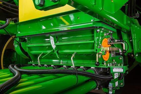
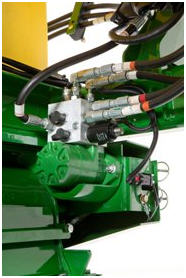
Primary manifolds
 Stationary double-shoot primary manifold
 Primary manifolds are mounted below the tanks with 63.5-mm (2-1/2-in.) diameter tubes to distribute seed/fertilizer evenly to the secondary manifolds, which are located on the seeding tool.
63.5-mm (2-1/2-in.) primary lines are clear with either a black or green spiral:
- Black spiral for single-shoot systems
- Black and green spiral for double-shoot systems
Stationary single-shoot or stationary double-shoot primary manifolds are available.
Single-shoot air systems are used when seeding only or when applying a starter fertilizer along with the seed. Double-shoot air systems are used when applying higher levels of fertilizer, allowing simultaneous application of seed and fertilizer by placing them in two different locations in the seed row. With the proper 1910 Cart configuration, starter fertilizer can also be applied with the seed in a double-shoot air system.
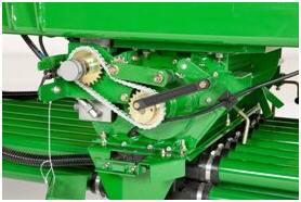
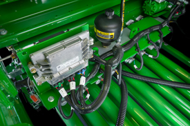
Hydraulic drives provide accurate metering and variable rate
Hydraulic drives
Starting in model year 2014, hydraulic drives became standard equipment on the 1910 air carts, offering consistent drive power to the meters. Hydraulic drives come standard with variable-rate drive and hydraulic calibration.
The drive system reduces a large number of mechanical and electrical components including transmissions, clutches, chain drives, sprockets, gears, and shafts by replacing them with a hydraulic drive motor, electrohydraulic valve, and a chain drive connecting the motor and meter.
Each meter has its own hydraulic drive motor and can be set independently of each other. It is recommended to use power beyond or another selective control valve (SCV) if power beyond is not available. Hydraulically powered meters minimize the pulsing effect found in chain driven systems. The motor speed is controlled by an electrohydraulic valve mounted on the motor.
Operators can shut off any meter from the in-cab display. The cart software comes with six pre-loaded rates for seeding. Map based prescriptions can be used with variable rates.
The system uses wheel speed from the cart to determine ground speed. If the cart wheel speed drops below 3.2 km/h (2 mph), the system will use tractor speed, if available, to maintain proper application rates when turning or coming out of a headland turn.
 Hydraulic drive motor
  Calibration tools and equipment
 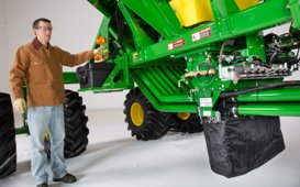 Operator performing calibration
 Variable rate
Starting in model year 2014, hydraulic variable-rate drive became standard equipment for 1910 air carts. Quick changing rates are important for maintaining accuracy with variable-rate prescription applications.
 Meter drive system
 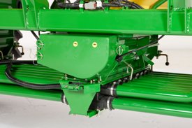 Meter drive system with safety shield installed
 Hydraulic calibration
Hydraulic calibration makes it convenient to rotate the cart meters to perform accurate calibration.
More than one meter can be calibrated at a time. Following the below instructions for 1910 air carts:
- Weigh bag, tare scale
- Add bag to bottom of meter
- Rotate the meters twice to charge them with product
- Turn the meters until they stop
- Weigh the bag with product inside
- Enter the weight of the product on the in-cab display
Meter verification
Operators can perform meter verification without driving. In the meter verification page on the in-cab display, select the meter(s) to verify and the stationary checkbox. When the operator engages the calibration switch, the meter will turn the number of revolutions to meter out the amount of product for the area selected.
NOTE: It is highly recommended to have power beyond and load sense installed on the tractor hydraulic system to power the hydraulic drives. This feature will save fuel, as well as reduce hydraulic heat, while providing maximum performance by the tractor hydraulic system to the cart hydraulic drive motors. By having load sense, the tractor is only required to provide the pressure and flow that the drives require. Power beyond and load sense capability have been tested and approved for all 8x00, 9x00, and newer John Deere tractors. Older John Deere tractors and competitive tractors have not been tested for functionality. If power beyond is not available, an additional SCV will be needed to power hydraulic drives. See link for more information on power beyond kits.
NOTE: Hydraulic drives cannot be retrofitted onto mechanical drive carts.
NOTE: For high application rates, it is recommended to utilize tractors with the hi-flow hydraulic pump option. See 1910 Commodity Cart tractor compatibility and requirements for more information.
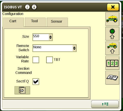
Take command of every acre and every input with SectionCommand™ system
SectionCommand is an effective, integrated, exclusive John Deere solution that reduces costly overlaps and skips that can waste seed and fertilizer, while offering more consistent fields that improve the potential of your yield and your bottom line.
Thanks to individual meter sections that control commodity flow, you can maintain the right application rates and row-to-row accuracy. This helps stimulate even crop emergence during the growing season and promotes consistent crop maturity at harvest. SectionCommand controls output from all meters on the cart up to eight sections.
Owner benefits include:
- Improved consistency of crop maturity at harvest
- Improved consistency during emergence and growing season
- Reduced seed input cost
- Reduced fertilizer input cost
- Increased time between fills due to input savings
SectionCommand is base equipment with optional deduct on all John Deere 1910 and C-Series Air Carts. Each tank and meter will receive SectionCommand components. A two-tank cart will control sections out of both tanks, a three-tank cart will control sections out of all three tanks, and the C-Series Air Carts will control sections out of all four tanks. SectionCommand is also available as an attachment for field conversion (AFC) for all 1910 hydraulic drive carts. See AFC kit story for more information.
SectionCommand controls seed and fertilizer output by closing and opening gates on the bottom side of the meter. When the gates are open, commodity is metered out, and when closed, commodity stays and continues to rotate within the meter. The meter stays full at all times so immediately when the gate opens, the commodity can flow into the primaries and out to the tool. Since each meter section has its own gate, application rates and row-to-row accuracy are not compromised. The gates are utilized to control commodity output on all sections. Once the last gate needs closed, the entire meter will stop turning, stopping product flow.
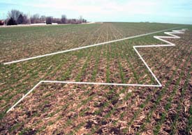 Seeded fields photo
 When commanded, electric over-hydraulic solenoids engage actuators to instantaneously close the gate for the needed section. The actuators are powered via hydraulics from the same circuit as the hydraulic drive motors. When power is cut, oil is diverted to retract the actuators and open the gates. The retraction is both powered and spring assisted, so it will always default to the seeding position. The oil from SectionCommand drains back through the fan motor case drain line and is coupled with an accumulator on the valve block to provide extra drainage capacity.
 SectionCommand components as seen on back side of meter
 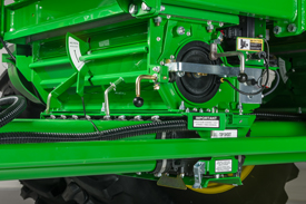 SectionCommand components as seen on front side of meter
 SectionCommand incorporates gate detection, which gives producers the satisfaction of knowing the gates are in position as commanded. Magnets on the back side of the gates are used in close proximity to the gate detection sensors to determine if the gates are open or closed. Should a gate not be in the commanded position, an alarm will alert the operator of the gate(s) in question. The blockage warning system works in conjunction with SectionCommand to give further confidence whether a given section is seeding or not when commanded.
 SectionCommand meter cartridge showing one gate closed and magnet on backside of gate
 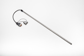 Gate detection sensor
 For maximum performance, SectionCommand should be controlled through John Deere Section Control. Coupling SectionCommand with John Deere Section Control provides the ultimate in precision seeding and productivity. If a Section Control activation is held by the producer, that same activation can be utilized for SectionCommand.
SectionCommand introduces the orange roller, which has the same number of flutes and spacing as the blue roller, but shorter flutes. It is for use only with SectionCommand when seeding seeds larger than 6 mm (0.25 in.) in diameter (soybeans, chick peas, etc.). The orange roller is not for use with cereal grains or fertilizer.
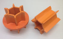 Orange roller for use only with large seeds and SectionCommand
 SectionCommand equalizer
Due to the varying lengths of product delivery hose used across the drill, SectionCommand has a built-in equalizer feature to ensure consistent product delivery across the width of the drill when entering and exiting headlands. The software allows the producer to set the on/off product delivery times separately for the outermost opener and the innermost opener on the drill. Product delivery times are inputted for each tank on the cart, and the software creates a time delay for actuation of the gates.
Please see the Using SectionCommand video for more information.
 Enabling SectionCommand equalizer
 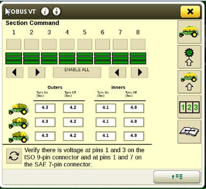 Input on/off times for outer opener versus inner opener on each tank
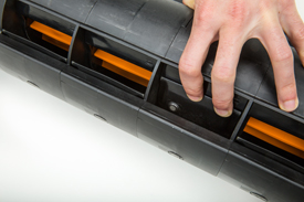
 Wirelessly controlled hydraulic conveyance reduces operator physical effort
Operators continually seek easier and faster operations while seeding and reduce time spent filling and unloading.
Conveyance on 12,334-L (350-bu), 15,200-L (430-bu), and 19,400 (550-bu) carts is controlled by hydraulic cylinders on the conveyance arms. The cylinders move the main arm, swing arm, and elevation. Now operators can easily deploy the conveyance system with less effort.
Input to the system is received from one of two remotes. Each operator receives a wireless remote that can be operated from anywhere near the cart and a tethered remote that can be operated from ground level near the front meter. Each remote controls the same functions and gives flexibility of system control should two operators be in the area during cart fill and unload.
The remotes can start, stop, and control speed of the conveyance system. For added security, the speed control arm is retained on the conveyance and can override the remotes to slow down or stop the belt or auger.
Securing the auger or conveyor is now easier and gives the operator a greater sense of security with over-center latches on both the top and bottom of the conveyance.
Both the main and swing arms are longer giving operators greater flexibility in tendering vehicle parking locations.
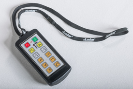 Wireless remote
 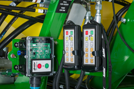 Receiver and tethered remote
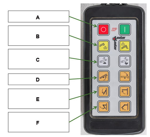
A - Remote on/off
B - Conveyance stop/start
C - Conveyance slow down/speed up
D - Tilt/elevation
E - Main arm retract/extend
F - Swing arm retract/extend
 Factory-installed hopper Left-hand side of cart in transport
 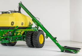 Left-hand side of cart in fill position
 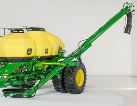 Left-hand side of cart in unload position
 SectionCommand™ system field conversion kit
SectionCommand is available as an attachment for field conversion (AFC) for all hydraulic drive carts. See SectionCommand saves seed and fertilizer input costs for more information on benefits and workings of the system.
 SectionCommand components on 1910 Cart with meter cartridge removed
 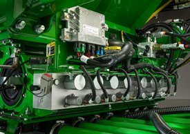 SectionCommand on 1910 Air Cart
 There are four main components needed to add SectionCommand onto 1910 hydraulic drive air carts:
1. SectionCommand AFC kit (listed in the table below, order one kit per meter), kit includes:
- SectionCommand valve block and meter housing components
- Gate detection controller
- Electronic power module (EPM)
- Associated harnessing, hardware, and brackets
2. Hydraulic hoses - Dealer is responsible for fabricating and sourcing hoses.
3. SectionCommand meter cartridges will be needed for each meter. These meter cartridges contain gates, gate detection sensors, and a secondary meter lock-down. See Meter cartridges for field conversion for more information.
4. New Operator’s Manual including SectionCommand. Order A98462 or newer 1910 operator’s manual when installing onto a model year 2013 19,400-L (550-bu) cart or all model year 2014 carts.
Ensure the latest version of software is installed on both cart controller and in-cab display.
All SectionCommand kits are sold in eight-run configurations. If pairing the cart with a tool of seven runs or less, order one - BA32812 meter run reduction kit per cart. This kit contains parts to block off runs not used when pairing a cart with a tool of seven runs or less.
NOTE: For SectionCommand to operate properly, it must be installed on each meter.
SectionCommand™ savings calculator assists operators in determining potential savings
To assist in determining savings potential for an operation when using SectionCommand, please utilize the savings calculator. A link is provided for access to the calculator.
Directions:
The savings calculator can calculate savings potential for up to three crops. Insert the variables into the yellow boxes for each of the three crops. Input variables include:
- Crop(s)
- Acres of each crop
- Seeding rate per acre
- Seed price per pound
- Fertilizing rate per acre
- Fertilizing rate per pound
Green boxes will list the potential savings per crop and total savings are listed at the bottom of the page.
1910 Cart brakes
 1910 Cart brakes
 Cart brakes are an option with 430 Tow Between, 430 Tow Behind, and 550 Tow Behind carts. The brakes are required when using a 18.3-m (60-ft) N560F Disk Drill or 23.2-m (76-ft) P576 Air Hoe Drill.
The air cart hydraulic brakes connect to the tractor’s hydraulics through a brake connection at the rear of the tractor. Tow behind carts require an extension hose for the air seeding tool.
The air cart brake system supplements the tractor brakes. The cart system senses when the tractor’s brakes are applied and engages a caliper on a rotor at each rear axle hub.
Ensure the tractor has a hydraulic brake port and is equipped with adequate ballast for the air cart and seeding tool.
Air Power™ 2 fan drive system
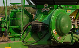 Air Power 2 fan drive system
 Enhanced air seeding performance would not be possible without the updates to the 15,152-L (430-bu) and 19,381-L (550-bu) 1910 and C850 air carts.
For the wider seeding width, more fan capacity has been added.
Air Power 2 provides two independently controlled fans – one for seed, one for fertilizer. Along with 76.2-mm (3-in.) primaries, more accurate delivery rates are possible across the full width of the seeding tool – from opener to opener. Air Power 2 delivers high rates, up to 40 percent more product delivery per primary compared to the single-fan system.
Dual fans are required for tow-between and tow-behind carts on the 23.2-m (76-ft) P576 and the 18.3-m (60-ft) N560F. Each fan will direct air to one set of primaries. Two selective control valves (SCVs) are required for the fans. The fan speed will be controlled through the SCV flow control.
Air Power 2 will also be compatible with:
- 17-m (56-ft) P556
- 13-m (43-ft) N543F
- 15.2- and 18.3-m (50- and 60-ft) 1890 models
An option is available for stainless-steel primaries to resist corrosion from high fertilizer rates.
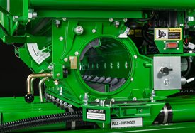
 C850 Air Cart
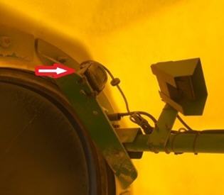
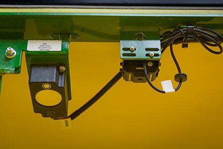
 There is a slide at the meter to choose bottom or top shoot for each product. There is also a valve on the tank pressure system to choose top or bottom shoot. This same valve is used to adjust the amount of air to the tank to create the proper pressure differential.
The arrow on the valve handle should be pointing to the top of the range for the top shoot and the bottom of the range for the bottom shoot. If the tank will not be in use, set the pressure valve to the middle setting to not pressurize the tank. The operator should use the gauge to find the correct setting. Location of pressure read-out:
- 1910 Tow-Behind left-hand side of cart on pressure gauge*
- 1910 Tow-Between front of the cart on pressure gauge*
- C850 Air Cart side display
* The electronic pressure sensor is located behind the mechanical gauge on the side of the cart.
For all Air Power 2 configured carts, an electronic pressure sensor will send a warning to the display if the tank pressure differential is out of range. If pressure is in the green operating range, the tanks are sealed and operating correctly.
Tank warnings on the GreenStar™ 3 2630 Display
NOTE: Only applies to 1910 AirPower 2 Carts as the C850 Cart is only compatible with the Gen 4 4600 CommandCenter™ or 4640 Universal Display.
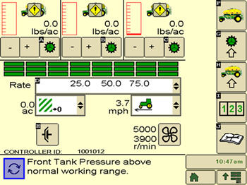 Tank warning on display
 The operator will receive a warning in the display if a tank’s pressure is above or below normal working range. There will be a warning sign over the tank with the out-of-range issue.
Select the icon to view the tank pressure screen.
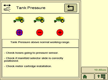 Tank pressure screen – plus indicates too much product
 The operator can press on the red warning and get a screen that looks like the picture above. The plus indicates the pressure is out of range and could be delivering too much product.
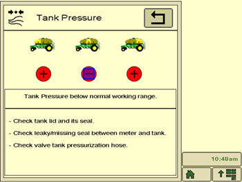 Tank pressure screen – minus indicate too little product
 The minus indicates the pressure is out of range and could be delivering too little product.
*Only applies to 1910 Air Power 2 Carts as the C850 Cart is only compatible with the Gen 4 4600 CommandCenter™ or 4640 Universal Display.
NOTE: A quick reference guide will ship with every operator’s manual. Please reference that and the operator’s manual for more detailed information.
Camera ready
Monitoring the product levels in tanks has never been easier with the camera-ready feature of the 1910 and C-Series Air Carts. The carts come pre-wired to accept a camera in each tank and on the rear of the machine. Cameras allow the operator to conveniently monitor product levels in each tank, which is especially reassuring when product levels are low. Cameras also provide the operator with visibility behind the cart when traveling down the road.
 Camera locations on the 1910 Air Cart
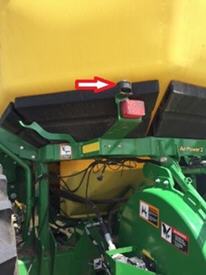
 Camera location on the C-Series Air Cart
 For the 1910 Air Carts, the producer has the choice of linking up to three cameras (CabCAM™ or Voyager® cameras) to a GreenStar™ 3 2630 Display or up to four Voyager cameras on a Generation 4 4600 CommandCenter™ Display or 4640 Universal Display. If the producer wants to view more than four cameras, a producer-purchased camera display will be needed.
For C-Series Air Carts, the producer can use up to four Voyager cameras on a Generation 4 4600 CommandCenter Display or 4640 Universal Display. If the producer wants to view more than four cameras, a producer-purchased camera display will be needed.
NOTE: Generation 4 displays only support Voyager cameras.
While the 1910 and C850 Air Carts come pre-wired to adapt cameras, additional harnesses are necessary for connecting to the tractor, and a tool overlay harness will be needed for tow-behind carts. Please use the option codes below if ordering on a new machine or the part numbers for configuring an existing machine.
Option code | Description | Parts |
9610 | Tool overlay harness | AA94564 |
9615 | Gen 4 4600 CommandCenter Display tractor cab harness | AA93727 (order one per camera) AA94316 |
9620 | 4640 Universal Display tractor cab harness | SWTY268456 AA94316 |
9625 | GreenStar 3 2630 Display tractor cab harness | AA94319 AA94316 |
Some carts may require SWVOSCCAM and AA96311, a Voyager connector to CabCAM connector, on the rear of the cart.
CabCAM is a trademark of ATI Products, Inc. Voyager is a trademark of ASA Electronics, LLC.