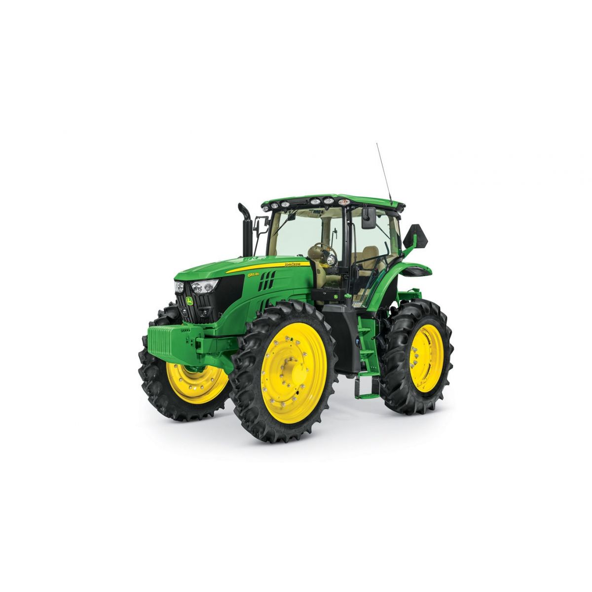
6155RH
Tractor
- PowerTech™ PVS 6.8 L (FT4)
- Category 3/3N, 3-point hitch
- MFWD
- ComfortView™ Cab
Features
Rear drop axle 6155R (hi-crop)
Overview
Exclusive to the 6155R Tractor, the optional rear drop axle provides additional crop clearance under the axle as well as additional drawbar clearance, when compared to a base axle with high clearance tires.
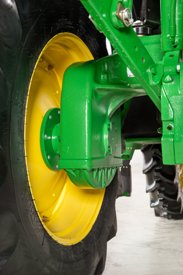 Rear drop axle
 Benefit
- Additional crop clearance
Details
The drop axle features a flanged-type axle end that provides up to a maximum drop of 295 mm (11.6 in.) and can accommodate tread settings from 1524 - 2235 mm (60 to 88 in.). The hi-crop option is only compatible with 18.4R38-in. 141A8 R2 rear and 320/90R46-in. 148A8 R2 radial front wheels and tires or 320/90R50-in. 147A8 R1W rear and 320/90R50-in. 147A8 R1W radial front wheels and tires.
Loaders are not compatible with this configuration.
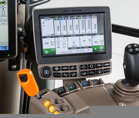
CommandCenter™ display
Overview
The Generation 4 CommandCenter creates the primary user interface for 6R, 7R, 8R/8RT, and 9R/9RT Tractors. The Generation 4 CommandCenter provides an excellent, user-savvy operating experience.
Producers can also use a variety of implements with the Generation 4 CommandCenter as it is ISOBUS virtual terminal (VT) capable.
Expect machine productivity gains, along with increased operator confidence, thanks to a simple, customizable interface. The reliability of the Generation 4 CommandCenter also aids in optimal operating experience and maximizes uptime.
 4200 CommandCenter 21.3-cm (8.4-in.) display
 Benefits
- Easy-to-change fields and guidance lines
- Custom-defined views
- On-screen help functions
- Intelligent warnings
- Context-based help
Details
| Code | Description |
| 1947 | 4200 Processor (21.3-cm [8.4-in.] display only) |
| Code | Description |
| 1829 | 21.3-cm (8.4-in.) CommandCenter display (4200 Processor only) |
| Code | Description |
| 1845 | Less activations |
| 1851 | CommandCenter AutoTrac™ activation |
| 1858 | Gen 4 CommandCenter AutoTrac activation with 4200 Section Control |
NOTE: CommandCenter AutoTrac activation stays with the tractor.
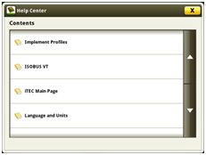 Help center main page
 Additionally, application-based help is also available in all locations of the CommandCenter. Simply click on the (i) icon available on the title bar and it will lead directly to more information on the application currently being used.
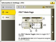 Context-based help iTEC™ main page
 Diagnostic text and information is available for better understanding of whether applications are operating as directed.
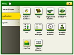
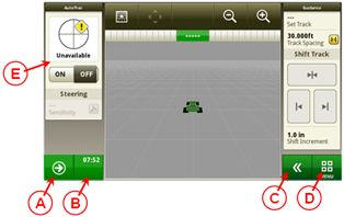 John Deere 4200 CommandCenter
 A. Next run page
B. Status center
C. Expand shortcut keys
D. Menu
Layout manager
 Layout manager selection page
 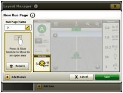 Layout manager module build
 The Generation 4 CommandCenter features a modular-designed layout manager, so an operator can easily create the structure that meets the operator’s demands. From the factory, machines are equipped with standard run pages. An unlimited amount of run pages can be added to the Generation 4 CommandCenter based on operator preference or operational needs. Toggling between run pages is as easy as swiping the screen or using the arrow buttons on the top right portion of the title bar.
Users and access
Users and access allow the owner to lock out certain functions to prevent operators from accessing or changing settings. Lock-out functions are managed with an owner-defined four-digit code.
Lockout features are available for:
- Precision Ag Technology applications
- Hitch
- Hydraulic
- Transmission
- Power take-off (PTO)
- FieldCruise™ engine controls
- Display
- Machine monitor
On-screen help and diagnostic text
There are several different ways to get meaningful on-screen help when navigating the Generation 4 CommandCenter. Operators can find the help icon on the shortcut bar on the bottom of every page. This icon gives detailed information on everything from tractor operation to application information. Simply select the help icon and navigate to the information section that is needed.
Machine Monitor
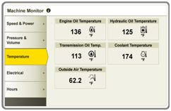 Machine Monitor page
 The Machine Monitor application provides the user instantaneous readings about the status or condition of the machine. Values shown in the machine monitor vary by application, but typically include parameters like engine speed, coolant temperature, and ground speed. The Machine Monitor supports run page modules in the layout manager, allowing the user to populate specific machine parameters directly to a run page.
NOTE: The Machine Monitor application replaces part of the Universal Performance Monitor in previous machines.
The 4200 Processor is base equipment on the 6155RH Tractor. It offers:
- Compatible with 18-cm (7-in.) touchscreen display
- One video camera input
- One USB input
- AutoTrac capable (machine-specific activation sold separately)
| Tractors | 4200 Processor |
| 6155RH | Standard |
Display options
Generation 4 CommandCenters are available in the following configurations:
- 21.3-cm (8.4-in.) display on the 4200 CommandCenter
Work Monitor
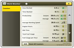 Work Monitor page
 The Work Monitor application displays the performance information about the task being performed by the machine. The user is shown averages, totals, and productivity of the machine, such as area worked, average working speed, and fuel usage. The values of the Work Monitor can be reset by the user at any time. Specific values of the Work Monitor can be configured by the user to be shown on a run page.
NOTE: The Work Monitor application replaces part of the universal performance monitor in previous machines.
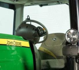
Video capability
Tractors with a 4200 CommandCenter are equipped with one video input . The operator can set a variety of triggers, including reverse, PTO, hitch, and selective control valve (SCV) levers to activate the camera. The image will then appear on the CommandCenter display. The camera (video observation system) is available through JD Parts and Ag and Industrial (A & I) Products.
John Deere Generation 4 CommandCenter processors
A Generation 4 CommandCenter is made up of a processor and a display.
Rear-mounted selective control valves (SCVs)
Overview
The selective control valves (SCVs) can be controlled electrically.. All mechanical or electrical SCVs feature four positions - neutral, raise, lower, and float.
Benefits
- Release levers make disconnecting hydraulic hoses easy
- Relocated valves improve operator's visibility to the rear hitch
| Code | Description | Information |
| 3332 | Three mechanical SCVs - premium | Premium couplers with high-pressure relief lever. Only in combination with PowrQuad™ Plus or AutoQuad™ Plus. |
| 3331 | Three electronic SCVs - premium | Premium couplers with high-pressure relief lever. |
Mechanical control valves
Overview
The tractor may be equipped with one type of mechanical control valves: premium (450 Series).
Premium-couplers control valves also have an additional lock function (position 3), which holds the control lever in the raise or lower position until the pressure in the oil circuit has reached a predetermined value (e.g., when the control cylinder has reached its end position).
In position 2, the control lever returns to neutral as soon as it is released and is the setting for normal hydraulic operation.
If an implement is connected, pressure connection must be connected to the lower coupler. With standard SCVs, a valve prevents sudden loss of pressure caused by leakage when the engine is shut off.
On premium SCVs, the likelihood of leakage is further diminished.
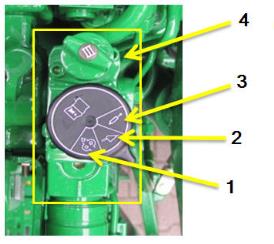 Premium mechanical control valve (premium)
 - Position 1
- Position 2
- Position 3
- Hydraulic oil flow control
Electrical control valves
Overview
The tractor may be equipped with the premium (450 Series) control valves. All main characteristics can be controlled by the CommandCenter™ display.
 CommandCenter hydraulics option
 Hydraulic control options
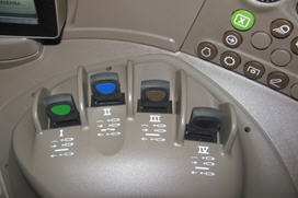 E-SCV controls on the right-hand console
 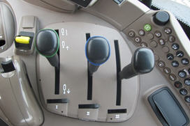 M-SCV controls on the right-hand console
 Hydraulic setup
Shortcut button right-hand console
Simply push the hydraulic symbol on the right-hand side console or the CommandCenter and the CommandCenter display shows a setup menu to:
- Monitor valve status - detent, float, or neutral
- Adjust maximum flow and detent (combine for both direction or separate extent and retract adjustment)
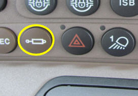 Hydraulic shortcut button on right-hand console
 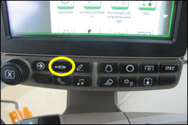 Hydraulic shortcut button CommandCenter
 Detent setup
- Time detent - this is particularly useful when repeat SCV operations are performed, such as lowering a mower-conditioner plow or cycling planter markers.
- Continuous flow detent - this is particularly useful when a hydraulic motor is used, such as on an air seeder.
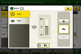 Detent setup
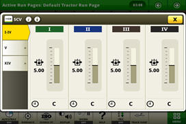
 SCV flow setup
SCV flow rate can be programmed between 0.04 and 10 allowing fine tuning for implements with different hydraulic requirement.
Behavior can be set between linear (red), progressive (green), or a combination (yellow) for exact flow modulation and precise valve management.
- Linear means that the distance travelled by the SCV/ICV corresponds to the distance travelled by the control lever/multifunction lever
- Progressive means that initially the distance travelled by the SCV/ICV is less than that travelled by the control lever/multifunction lever (giving a more sensitive start to the movement)
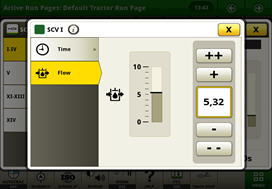 Flow setup
 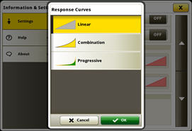 Three flow options
 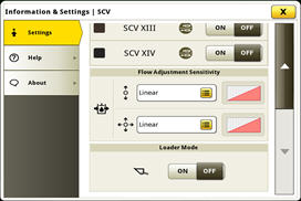 Flow characteristic setup
 Combination is an intermediate stage between the two settings listed above.
ComfortView™ operator environment
Overview
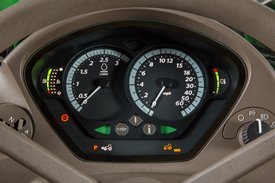
ComfortView cabs feature a modern, automotive-style instrument panel as base equipment. The instrument pod has two large analog dials for engine and tractor speed, as well as two smaller dials that display fuel level, DEF level, and coolant temperature. The steering column and dash are adjustable to suit the operator's needs. The column tilts toward the operator and a lever on the left-hand side allows for the column to telescope out to the desired level.
A dimming mode automatically reduces the brightness of the instrument illumination when the tractor lights are used.
Steering column control panel
 Cab and controls 6R Tractor
 Instrumentation control panel
Overview
The instrumentation panel has a row of information and warning lights across the bottom to monitor all important tractor functions. A three-stage warning system first gives information, then gives warnings, and finally, gives a stop alarm to prevent damage from occurring in the event of a component malfunction. An integrated power take-off (PTO) over-speed warning is incorporated into the diagnostics to ensure proper operation.
 Instrumentation control panel
 Dash instrument panel controls include:
| Left side | Right side |
| Left-hand reverser | Two-speed and optional intermittent wiper |
| High-/low-beam switch | Key start/stop |
| Hazard switch | Road/work lights on/off |
| Turn signals/horn |
In-cab storage
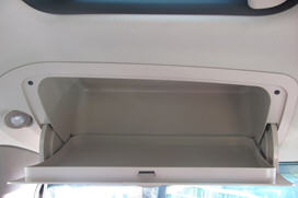 Overhead storage compartment
 Right-hand console controls
Overview
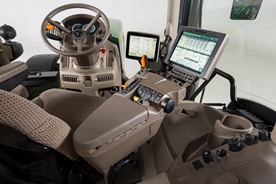
The right-hand control console is angled for operator comfort and ease of operation. The design of the right-hand console is controlled by the type of SCVs chosen.
Mechanically actuated valves are controlled by traditional levers, while electronically actuated valves are controlled by fingertip paddle pods. Controls for the ComfortView cab are grouped by function on the right-hand console.
The modular console panel provides individual access to hand throttle, transmission controls, MFWD switch (if equipped), hitch command console, load/draft control, SCV, and PTO controls.
The console is also the location of the CommandCenter. The CommandCenter allows the operator to customize important tractor functions.
This option requires a PowrQuad™ or AutoQuad™ transmission.
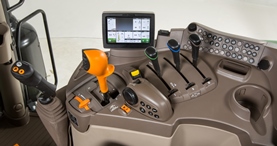 ComfortView cab right-hand console (AutoQuad transmission is shown)
 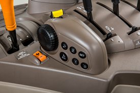 Hitch control module on right-hand console
  M-SCV controls on the right-hand console
  E-SCV controls on the right-hand console
 Benefits
- Ergonomic placement of controls to match arm movements
- Integrated hitch control module with draft wheel
Cab packages for 6155RH
| Cab packages | Economy right-hand console | Standard right-hand console | Premium right-hand console | Premium right-hand console cab suspension |
| Package code | 2051 | 2061 | 2065 | 2069 |
| One panorama door (left hand only) | X | X | ||
| Two panorama doors (left-hand and right-hand sides) | X | X | ||
Air seat (Sears) | X | X | X | |
| Deluxe air seat (Grammer® DDS) | X | |||
| Instructional seat | X | X | X | |
| Bottle holder | X | X | X | |
| Mirrors - right hand and left hand - manually adjustable and telescopic | X | X | ||
| Wide-angle mirrors - right hand and left hand - electrically adjustable | X | X | ||
| Front sun visor | X | X | ||
| Front and rear roller blind | X | X | ||
| Rear wiper and washer | X | X | X | |
| Manual temperature controls | X | X | ||
| Automatic temperature controls | X | X | ||
| Hydraulic cab suspension | X |
*NOTE: 6155RH right-hand console only
Grammer is a trademark of Grammer AG Aktiengesellschaft.
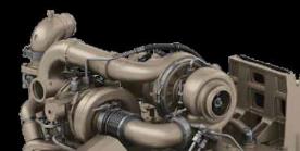
PowerTech™ PVS/PSS Stage 4 engine
Overview
John Deere 6R Series Tractors feature the reliable and proven PowerTech PVS 6.8L (415-cu in.) and PSS 4.5L and 6.8L (275-cu in. and 415-cu in.) engines. These air-to-air aspirated engines deliver a power bulge above rated power to provide excellent torque in demanding applications.
Key features:
- Series turbochargers (PSS only)
- Variable geometry turbocharger (VGT)
- Air-to-air after cooling
- High-pressure common rail (HPCR) fuel system
- Engine control unit (ECU)
PowerTech PSS/PVS engine identification
 | After treatment
|
Turbocharger
| |
Technology
|
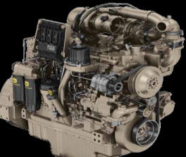 PowerTech PSS 6.8L (415-cu in.) engine
 Benefits
- A constant power range of 2100 rpm down to 1500 rpm
- Power bulge of 10 percent
- Greater tractor productivity
- Responsive power reducing the need to downshift the transmission
Details
To match the engine power characteristics and improve the operation economy of the machine, the rated engine speed is 2100 rpm.
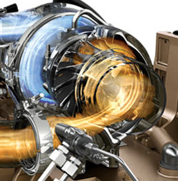
Series turbochargers
Overview
The PowerTech PSS 4.5L and 6.8L (275-cu in. and 415-cu in.) engines utilize two turbochargers – a VGT and a fixed geometry turbocharger, providing the torque rise and engine response needed to meet varying load conditions.
Fresh air is first drawn into the low-pressure fixed geometry turbocharger and compressed to a higher pressure. The compressed, higher pressure air is then drawn into the high-pressure VGT, where the air is further compressed. By splitting the work between two turbochargers, both can operate at peak efficiency and at slower rotating speeds.
Engine control unit (ECU)
Overview
The ECU uses signal inputs from sensors and pre-programmed performance modeling to control critical engine functions such as fuel quantity, injection timing, air-to-fuel ratio, multiple fuel injections, amount of cooled exhaust gas recirculation (EGR), and a host of other control parameters.
 PowerTech PSS engine series turbochargers
 Benefits
- Deliver high power density
- More low-speed torque and responsiveness to meet varying load conditions
 PowerTech VGT
 Benefits
- Increased low rpm torque
- Quicker response to load
- Increased peak torque
- Improved fluid economy
- Improved performance at high altitudes
VGT
Overview
The VGT is electronically controlled and actuates the turbo vanes as required to maintain peak engine performance.
The turbocharger’s vanes are in the exhaust flow. The opening or closing of the vanes changes the outlet volume and airflow speed against the turbocharger turbine. When exhaust flow is low, the vanes are partially closed. This partial closure increases the pressure against the turbine blades to make the turbocharger spin faster and generate more boost pressure.
The ability to keep the airflow at optimum levels provides more consistent engine boost pressure and the ability to respond to load quickly across the entire engine rpm range. This system is without the turbo lag that can be found on some engines.
Air-to-air after cooling
Overview
Air-to-air after cooling lowers the intake manifold air temperature and provides more efficient cooling while reducing cylinder firing pressure and temperatures for greater engine reliability. Since lower temperature air is denser, a higher volume of air flows into cylinders so the engine is capable of meeting the increasing horsepower demands. Lowering the intake manifold and cylinder temperatures also aid in lowering the combustion temperature, which lowers the NOx produced as a result.
Benefits
- Higher horsepower
- Less NOx production
HPCR fuel injection system
Overview
Every PowerTech PSS 4.5L and 6.8L (275-cu in. and 415-cu in.) engine utilizes a HPCR fuel system to efficiently supply fuel to injectors. The high-pressure fuel pump instantly responds to requirements for more or less fuel flow or pressure. This electronically controlled, high-pressure pump delivers pressure on demand according to the application requirements. Pressure on demand ensures an efficient injection system resulting in high-injection pressure independent of engine speed.
 High-pressure common rail
 Benefits
- Instantly respond to load changes reducing the need to change gears
- Improved fluid economy
 ECU
ECU Benefits
- Optimized fluid economy
- Maximum engine performance
Details
Each injector is controlled individually by the ECU. The ECU turns the injector on and off during each firing cycle to control the fuel delivery into each cylinder.
Load and speed sensing allow each cylinder’s fuel delivery rate to be adjusted independently at the individual injector. With each injection cycle, the ECU can make the following adjustments on the go:
- Number of injections
- Fuel pressure in the common rail
- Start of injection
- Duration of injection
This management system is connected to the transmission, allowing the engine and transmission to respond simultaneously.
Cold weather and high-altitude compensation are also precisely controlled for quality starts regardless of weather and maximum performance at high elevations. The ECU also features improved diagnostic capabilities. It is faster, has more working memory, and is responsible for monitoring and executing all aspects of the Integrated Emission Control System.
Lighting options provide maximum visibility in every direction
Overview
Lights on the 6R Series Tractors have been positioned and designed to provide maximum visibility to the front, sides, and rear of the tractor to increase productivity in any operating condition. The cab lighting pattern provides 330 degrees of coverage while the hood lighting provides the remaining 30 degrees, for completely programmable, 360-degree, stadium-style lighting.
Base lighting
- Two HB3 hood road lights - low beam (A)
- Two HB3 hood road lights - high beam (B)
- Two HB3 hood outer work lights (C)
- Two H4 belt-line lights (F)
- Four HB3 halogen inner front-roof-mounted adjustable work lights (H and I)
- Two HB3 halogen inner rear-roof-mounted adjustable work lights (N)
- Brake lights rear fender mounted (R)
Code | Hood | Belt | Front roof | Side | Rear roof | Fender | |||||||||
A | B | C | E | F | G | H | K | I | L | N | O | P | R | ||
| * Base package - with non-panorama roof | HB3 | HB3 | HB3 | NA | H4 | X | HB3 | HB3 | HB3 | X | HB3 | ||||
| Light package - Standard | 873F | HB3 | HB3 | HB3 | NA | H4 | X | HB3 | X | HB3 | HB3 | HB3 | X | HB3 | HB3 |
| Light package - Premium | 873E | HB3 | LED | LED | NA | LED | X | LED | X | LED | LED | LED | X | LED | HB3 |
| Light packages panorama roof code (878W) | |||||||||||||||
| Light package - Standard - panorama roof | 873A | HB3 | HB3 | HB3 | NA | H4 | X | LED | X | HB3 | HB3 | X | HB3 | HB3 | |
| Lighting package – Panorama light package | 873C | HB3 | LED | LED | NA | LED | X | LED | X | LED | LED | X | LED | HB3 | |
Light-emitting diode (LED)
High-intensity discharge/Xenon (HID)
Halogen (HB3)
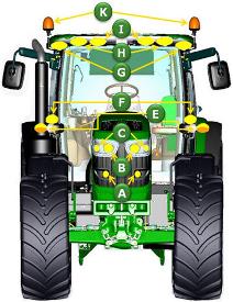 Lighting identification from front view of tractor
 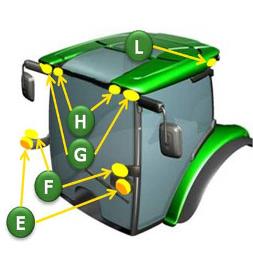 Lighting availability on panorama roof
 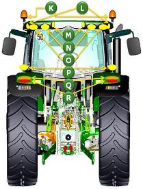 Lighting identification from rear view of tractor
 NOTE: Please also see available attachments.
Selecting the lighting mode
Overview
Operators can quickly select a lighting mode on the steering console by operating a rotary switch. The three settings available are:
- Light switch in the off position
- Headlights in road mode
- Headlights and work lights in field mode (depending on CommandCenter™ display assignments)
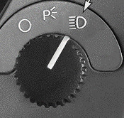 Lighting control switch on dashboard
 Benefits
- Easy to locate and operate
- Small and compact design
Programmable lighting
Overview
The CommandCenter allows operators to customize two different light programs. The operator can switch between the two programs with the push button. Also standard on the 6R Tractors is the battery power-saver feature. When the engine is off and the outside lights have been left on, this feature is designed to avoid battery run-down. After the lights have been left on for 30 minutes and the key is in the off position, the lights will cycle, or blink on and off, five times as an alert. The lights will continue to illuminate for one more minute and then automatically shut off to protect the battery.
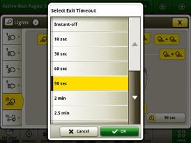 CommandCenter programmable timeout lighting
 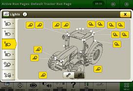 CommandCenter programmable lights page
 More lighting information
Optional LED lighting technology provides better depth perception and pattern recognition as well as a natural low temperature light for excellent definition of the field. One LED light will out-live 200 or more incandescent lights, 55 or more halogen lights, and 14 or more HID lights.
Two beltline work lights - LED
 Two beltline work lights – LED
 Benefits
- Less eyestrain on approaching traffic when traveling on the road.
- Saves the operator on service time and money and minimizes downtime.
- The LED bulbs and diodes have an outstanding operational lifetime to last the tractor's full running lifetime, thus giving the operator greater uptime.
Details
- Mounted at beltline at front of cab.
- No hanging work lights are possible. Not in combination with second beltline lights (873M and 873O).
| Code | Description |
| 873C | Part of Premium panorama roof light package |
873E | Part of Premium light package |
NOTE: Please also see available attachments.
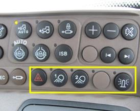 Beacon lights/hazard warning lights, work light 1 and 2 location on right-hand console
 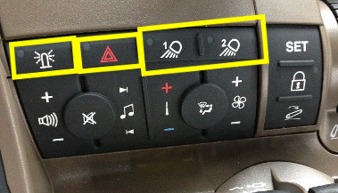 Beacon lights/hazard warning lights, work light 1 and 2 location on CommandCenter
 Benefits
- The John Deere light programming adds high performance to the operator.
- Individual light selection adds to high operator performance to prevent blinding other operators when two machines are working close to each other.
- Improved uptime due to 360-degree lighting.
Beltline and rear fender work lights
Overview
Beltline and rear fender work lights provide options for full light flexibility, giving flood illumination exactly where the operator needs it. The John Deere beltline lights are available with HB3 work lights and LED work lights. The two rear fender lights are available in HB3 or LED.
The John Deere lighting components have undergone numerous vibration testing procedures to ensure a good lighting performance and sturdiness under all conditions.
All work lights and beltline lights are adjustable to a desirable angle.
Two beltline lights - H4
 873M - Two beltline lights – H4
 Benefits
- The two beltline lights provide greater illumination toward the front wheels of the tractor.
Details
- Mounted at beltline at front of cab
- No hanging work lights are possible. Not in combination with second beltline lights (code 873M and 873O).
| Code | Description |
| 873A | Part of Standard panorama roof light package |
| 873F | Part of Standard light package |
NOTE: Please also see available attachments.
Benefits
- To warn other road users of the presence of a large machine on the road.
- Easily removed with no tools required when approaching height restricted areas.
- Waterproof to ensure good performance when required.
- The beacon has a degree of flexible movement, are not completely static, and can withstand the impact of objects such as tree branches.
Details
- Front cab is roof mounted.
| Code | Description |
| 873A | Part of Standard panorama roof light package |
| 873C | Part of Premium panorama roof light package |
| 873F | Part of Standard light package |
| 873E | Part of Premium light package |
Two rear fender work lights – LED
 Two rear fender work lights – LED
 Benefits
- The John Deere lighting components have undergone numerous vibration testing procedures to ensure a good lighting performance and sturdiness under all conditions.
- The LED rear fender light adds extra lighting when operating implements close to the ground.
NOTE: These lights should not be operated during road transport.
| Code | Description |
| 873C | Part of Premium panorama roof light package |
| 873E | Part of Premium light package |
NOTE: Please also see available attachments.
Two rear fender work lights – HB3
 Two rear fender work lights – HB3
 Benefits
- The two rear HB3 work lights, ensure good performance for the cost-sensitive producer.
NOTE: These lights should not be operated during road transport.
| Code | Description |
| 873A | Part of Standard panorama roof light package |
| 873F | Part of Standard light package |
NOTE: Please also see available attachments.
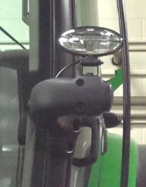
Beacon light for added visibility
Overview
A beacon light is mounted on the front of the cab to provide a rotating warning light for road traveling and added visibility.
StarFire™ 6000 Receiver
The John Deere StarFire 6000 Receiver is an enhanced replacement for the StarFire 3000 Receiver and expands on the value that precision agriculture growers have come to expect from StarFire products. The StarFire 6000 Receiver implements an improved antenna, the latest in Global Navigation Satellite System (GNSS) signal processing technology, and a differential correction signal. This technology adds up to improved performance and uptime as well as lower cost of operation when paired with precision agriculture systems such as AutoTrac™ assisted steering system and John Deere Section Control.
Customer value:
- Customize accuracy and repeatability to meet the needs of the operation
- Get started faster with improved pull-in performance
- Maximize uptime to keep the job moving
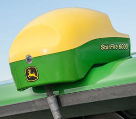 StarFire 6000 Receiver
 Non-John Deere guidance compatibility activation
With the non-John Deere guidance system compatibility activation, third-party guidance systems can be used with John Deere steering system components such as the steering valve, wheel angle sensor, and steering control unit found in 6R, 7R, 8R, 9R, and 9RX Tractors. For model year 2011 to 2019, 7R/8R/9R with ActiveCommand Steering (ACS™), 8RT, 9RT, or 9RX Tractors, see CCMS solution 118854.
The activation from John Deere enables communication between the non-John Deere guidance system and the tractor. Tractor owners who are interested in this technology should consult with a guidance system supplier for compatibility information as additional hardware, harnesses, and software from the supplier is also required for a fully functional system.
The chart below details which tractors will require this activation to operate a non-John Deere guidance system.
Non-John Deere guidance activations
| Model year 2011 | 7R Tractors 8R Tractors 8RT Tractors 8R |
| Model year 2012 and newer | 6R Tractors* 7R Tractors 8R and 8RT Tractors 9R and 9RX Tractors |
*6R Tractors also require iTEC™ headland management system (in base on Waterloo-produced 6Rs and optional equipment on Mannheim-produced 6Rs produced before model year 2015).
AUNZ Dealers Note: Mannheim 6R iT4 and 6R FT4 both MY17 and earlier will require the iTEC Headland Management System kit. 6230R and 6250R machines are the exception as the software is already in base. To order the kit, go to Techpubs.deere.com. Please order the software through JD Point after checking the Installation Instructions.
| 6R iT4 (MY17 and prior) | 6R FT4 (MY 17 and prior) | |
| Kit | AL208644 | BLI5374 |
| Installation Instructions | MHM1551 | MHM1618 |
Optimize John Deere Section Control performance
Section Control improves placement of agricultural inputs and reduces operator fatigue by automatically turning implement sections on and off. Section Control functionality is part of the Gen 4 CommandCenter™ Premium activation, 4640 Premium subscription, and 4240 Section Control and Data Sync subscription, allowing growers to automatically control up to 255 sections.
- For compatibility information, reference Generation 4 Display compatibility.
Using Section Control reduces the risk of improper placement of agricultural inputs. In addition, Section Control improves efficiency of producers by:
Reducing seed costs by an average savings of 4.3 percent (see reference below).
Optimizing yield by preventing double application of seed that studies suggest reduces inputs between 1 to 12 percent yield loss (see reference below).
Reducing operator fatigue, allowing for more operational hours in the field
Gen 4 Section Control functionality adds several features and ease-of-use improvements:
- Section Control tuning
- Plant-to-row capabilities
- On/off shortcut key
- Section status module
- Ability to turn boundaries off for Section Control while continuing to use them for documentation and Field Locator
- Section Control diagnostic table
Optimize Section Control tuning for skips and overlaps
Using Section Control tuning, operators can take the calculations or guesswork out of optimizing Section Control. The appropriate on/off time adjustments can be made by simply entering distances and operating speed. The Section Control application makes the necessary changes to the system.
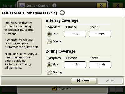 Section Control performance tuning
 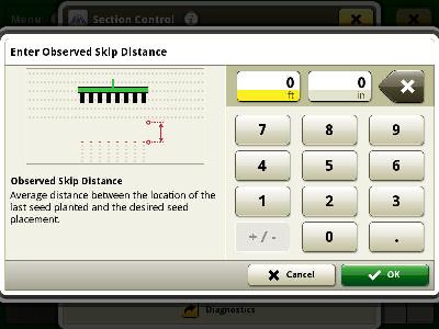 Reducing skips
 Section Control performance tuning enables operators to tune planter mechanical delay on and off times to the seed in the last outer headland row when used with planters. In planting operations, the performance tuning system is designed to adjust mechanical delay on and off times so that seed is placed at the intersection of two perpendicular passes. For other Section Control enabled operations, performance tuning places product at the coverage boundary.
Flexible operation with the section status module
Using layout manager, the section status module can be placed on any run page the operator would like, allowing them to monitor Section Control performance from any screen. Depending on operator preference, the implement screens can also be viewed using the split-screen ISOBUS implement modules.
Plant-to-row enables additional customization of Section Control performance
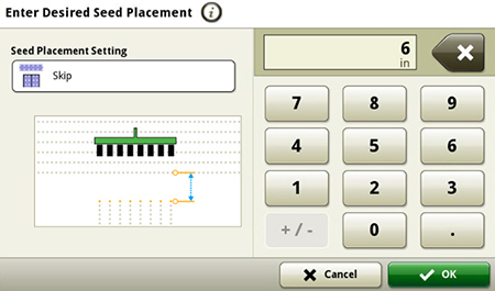 Seed Placement Settings of plant to row (default), skip or overlap
 Plant-to-row functionality allows producers to customize the in-line skip or overlap observed at the intersection of a perpendicular planting pass. Default Performance Tuning settings command the planters mechanical delay times to place seed at the intersection of the last outer headland row. For example, producers who want a 15.2-cm (6-in.) skip to allow the corn head snoot to pass between rows would set a 15.2-cm (6-in.) skip within the Seed Placement Settings.
Turn Section Control on or off from any run page
If an operator chooses to use the Section Control shortcut as one of their shortcut buttons, they can quickly turn Section Control off for manual implement operation from any run page. Operators can configure the Section Control on/off shortcut button in layout manager.
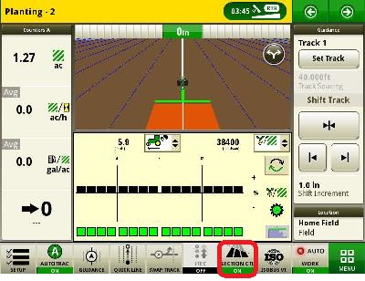 Section Control on/off shortcut
 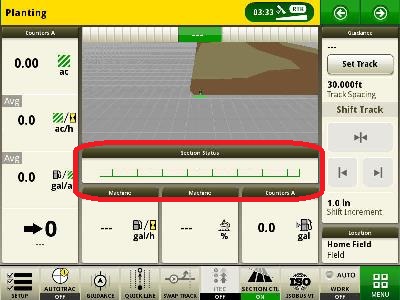 Section status module
 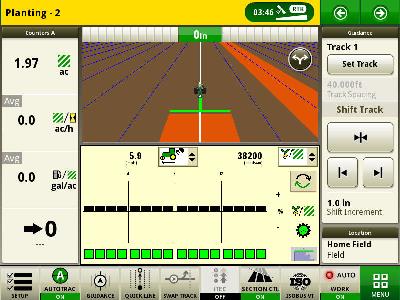 John Deere planter ISOBUS implement split screens
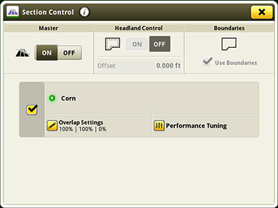
 Boundaries and Section Control
Section Control is also capable of preventing application of inputs outside of a field boundary, inside an interior field boundary, or outside of a headland boundary. Boundaries can be created by manually driving the perimeter, from coverage created within the John Deere Operations Center and sent to the 4200 or 4600 CommandCenter Display/4240 or 4640 Universal Display, or can be imported from a GreenStar™ 3 2630 Display, APEX™ software, or another Gen 4 display.
- Enabling headlands allows operators to plant the headlands after the interior of the field has been planted.
- Turning boundaries off provides operators with the flexibility to apply product outside of the field boundary while continuing to use the boundary for field totals, documentation, or field location.
 Section Control
 Section Control diagnostics
 Access the Section Control diagnostic table to view the operation status and reason for the status
 To understand application performance more easily, the Section Control diagnostic table has been added. From the table, operators can easily identify the Section Control commanded state; this shows if sections are on or why the section is commanded off.
For example, if a section was over an area that has previous coverage and is outside of an exterior headland boundary, the diagnostic page will only display the exterior headland boundary. This page is intended to be used during operation for diagnostics, not when stationary. If attempting to use while stationary, all sections will show as off, with the reason indicating that the machine is below the minimum speed threshold.
Agricultural Industry Electronics Foundation (AEF) certified ISOBUS TC-SC implement compatibility
AEF ISOBUS Task Controller Section Control (TC-SC) compatible implements utilize the Gen 4 4200/4600 CommandCenter and 4640/4240 Universal Display as a virtual terminal that serves as the operator interface for the implement. Section Control functionality is capable of automatically controlling the sections on AEF ISOBUS TC-SC compliant implements. Implement compatibility can be checked using the database available at the AEF website.
Display compatibility
For compatibility information reference Generation 4 Display compatibility.
Reference: M. Runge, J. P. Fulton, T. Griffin, S. Virk, A. Brooke. Oct 2014. Automatic Section Control Technology for Row Crop Planters. Extension Alabama A&M & Auburn University ANR-2217