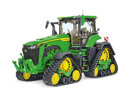
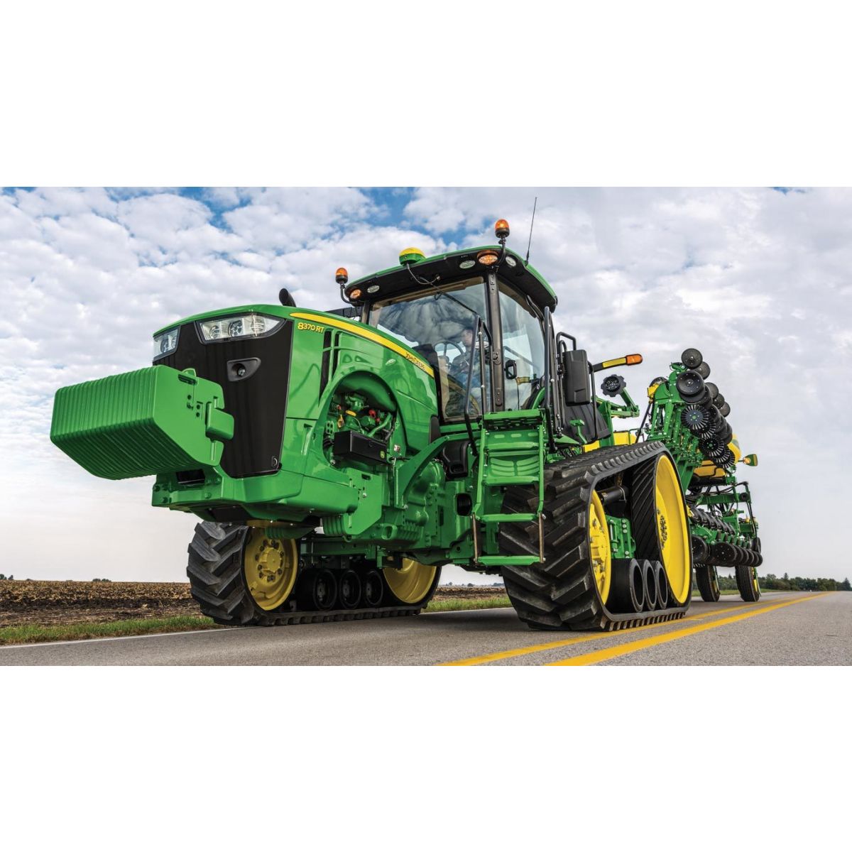
8370RT
Tractor
- 276 kW (370 hp) engine power
- John Deere PowerTech™ 9 L PSS
- Choice of e23™ PowerShift, or Infinitely Variable Transmission (IVT™)
- New cab suspension system and CommandView™ III cab and Generation 4 CommandCenter™
Features
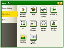
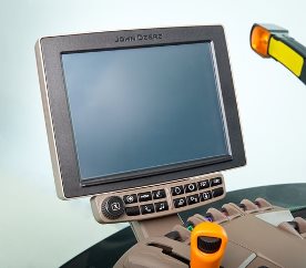
Take advantage of the Generation 4 CommandCenter™ display, designed for efficiency
The 4100 and 4600 CommandCenter, also known as the Generation 4 CommandCenter, creates the primary user interface for 6R, 7R, 8R/8RT, and 9R/9RT/9RX Tractors. The Generation 4 CommandCenter provides an excellent, user-savvy efficient operating experience.
Producers can also use a variety of implements with the Generation 4 CommandCenter as it is ISOBUS virtual terminal (VT) capable.
Expect machine productivity gains, along with increased operator confidence thanks to a simple, customizable interface. The improved design of the Generation 4 CommandCenter also aids in an optimal operating experience and maximizes uptime.
Some of the easy-to-use benefits of the Generation 4 CommandCenter include:
- Easy-to-change fields and guidance lines
- Custom-defined views
- On-screen help functions
- Intelligent warnings
- Context-based help
- Ability to import, export, and delete files
Layout manager
 Layout manager selection page
 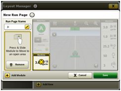 Layout manager module build
 The Generation 4 CommandCenter features a modular-designed layout manager, so an operator can easily create the structure that meets the operator’s demands. From the factory, machines are equipped with default run pages. An unlimited amount of run pages can be added to the Generation 4 CommandCenter based on operator preference or operational needs. Toggling between run pages is as easy as swiping the screen or using the arrow buttons on the top right portion of the title bar.
Users and access
Users and access allow the owner or manager to lock out certain functions to prevent operators from accessing or changing settings. Lock-out functions are managed with a defined four-digit code.
Lock-out features are available for:
- Ag Management Solution (AMS) applications
- Hitch
- Hydraulic
- Transmission
- Power take-off (PTO)
- FieldCruise™ system
- Display
- Machine monitor
On-screen help and diagnostic text
There are a number of different ways to get meaningful on-screen help when navigating the Generation 4 CommandCenter. Operators can find the help icon on the shortcut bar on the bottom of every page. This icon gives detailed information on everything from tractor operation to application information. Simply select the help icon and navigate to the information section that is needed.
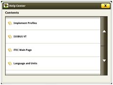 Help center main page
 Additionally, application-based help is also available in all locations of the CommandCenter. Simply click on the {i} icon available on the title bar and it will lead directly to more information on the application currently being used.
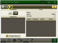 Context-based help icon
 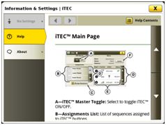 Context-based help iTEC™ system main page
 Diagnostic text and information is available for better understanding of whether applications are operating as directed.
Machine monitor
 Machine monitor page
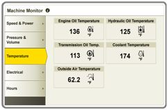
 The machine monitor application provides the user instantaneous readings about the status or condition of the machine. Values shown in the machine monitor vary by application, but typically include parameters like engine speed, coolant temperature, and ground speed. The machine monitor supports run page modules in the layout manager, allowing the user to populate specific machine parameters directly to a run page.
NOTE: The machine monitor application replaces part of the universal performance monitor in previous machines.
File manager
 File manager icon upper right
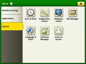
 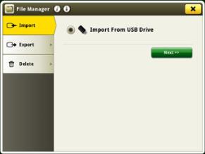 Options available in file manger
 File manager is located on the system page in the menu. Users can export, import, or delete single files or all files with the Generation 4 CommandCenter. Files can be imported exported, or deleted with the following filter options:
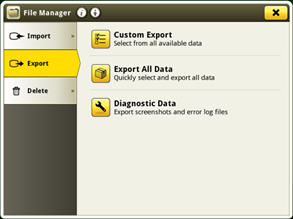
Export to USB
 Screen to export using USB
 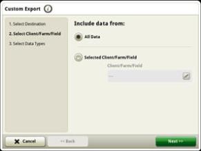 Choose all data or select client/farm/field
 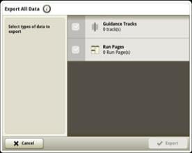 Choose specific guidance tracks or run pages
 - Choose to export all data types
- Select custom export to filter by individual client/farm/field and then export. In addition, users can filter by data type of guidance tracks or run pages.
Delete capabilities
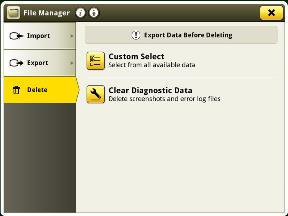
- Choose to delete all data types
- Select custom delete to filter by individual client/farm/field and then delete. In addition, users can filter by data type of guidance tracks or run pages.
Setup data
Users manage all setup data in John Deere Operations Center when using a 4100 or 4600 CommandCenter. Setup files transfer between displays via USB, for customers using GS3 2630 Display and Generation 4 CommandCenter in their operations.
Import from USB
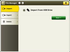 1. Screen to import using USB
 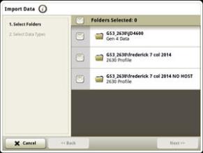 2. Select correct folder for import
 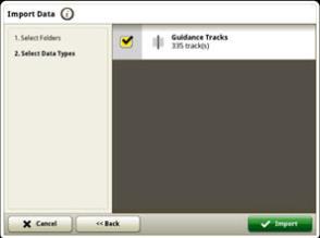 3. Select data type
 - Choose to import folder (like GreenStar™ 3 [GS3] 2630 Display select profile)
- Users can select by data type of guidance tracks or run pages.
Users can add one or more guidance lines, clients, farms, or fields without overwriting all of the information on the display.
Users can import a single item from the John Deere Operations Center without having to recreate the entire display database.
This ensures integrity of existing data on the display and improves data transfer time.
 4100 CommandCenter 177.8-mm (7-in.) display
| Tractors | 4100 Processor | 4600 Processor |
| 6R (AutoQuad™ transmission/CommandQuad™ transmission) | Standard | Not available |
| 6R (IVT transmission/DirectDrive), 7210R, 7230R | Standard | Option |
| 7250R, 7270R, 7290R, 7310R, 8R/8RT, 9R/9RT/9RX | Not applicable | Standard |
Work monitor
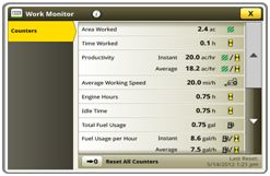 Work monitor page
 The work monitor application displays the performance information about the task being performed by the machine. The user is shown averages, totals, and productivity of the machine, such as area worked, average working speed, and fuel usage. The values of the work monitor can be reset by the user at any time. Specific values of the work monitor can be configured by the user to be shown on a run page.
NOTE: The work monitor application replaces part of the Universal Performance Monitor in previous machines.
 4600 CommandCenter 254-mm (10-in.) display
 The 4100 Processor is base equipment and only offered on 6R, 7210R, and 7230R Tractors. It offers:
- Compatible with 177.8-mm (7-in.) touchscreen display
- One video camera input
- One USB input
- AutoTrac capable (machine-specific activation sold separately)
Dual display mode
 Dual display
 The GS3 or GS2 Display can run in dual display mode with the Generation 4 CommandCenter.
Generation 4 CommandCenter may be configured to run with the following John Deere displays connected at the cornerpost:
- GS2 1800 Display
- GS2 2600 Display
- GS3 2630 Display
All precision activations purchased on GS2 or GS3 Display are defaulted to run on the cornerpost display while in dual display mode. Activations cannot be shared between GS2 or GS3 Displays and the Generation 4 CommandCenter. The second display must have its own activations to run AMS applications. RDA can be used on either GS3 2630 Display or Generation 4 CommandCenter in the same session.
Precision ag applications, such as AutoTrac™ assisted steering system, Section Control, and documentation, cannot run on both displays at the same time. When a cornerpost display is installed, precision ag applications will automatically be disabled on Gen 4 CommandCenter.
Tractor applications will always be located on the Gen 4 CommandCenter.
View on screen help to properly set up display when in dual display mode.
Video capability
Tractors with a 4100 CommandCenter are equipped with one video input and 7R, 8R/8RT, 9R/9RT/9RX Tractors with a 4600 CommandCenter have four video inputs. 6R Tractors equipped with a 4600 CommandCenter have two video inputs. The operator has the ability to set a variety of triggers, including reverse, power take-off (PTO), hitch, and selective control valve (SCV) levers to activate the camera. The image will then appear on the CommandCenter display. The camera (video observation system) is available through JD Parts and Ag and Industrial (A and I) Products.
John Deere Generation 4 CommandCenter processors
A Generation 4 CommandCenter is made up of a processor and a display. Two processor options are available for the Generation 4 CommandCenter.
The 4600 Processor is the premium processor, offered as an option on all 6R*, 7210R, and 7230R Tractors and is standard on 7250R, 7270R, 7290R, 7310R, 8R/8RT, and 9R/9RT/9RX Tractors. Available features with the premium processor include:
- Compatible with 254-mm (10-in.) touchscreen display
- Four video camera inputs
- Four USB inputs
- AutoTrac capable (machine-specific activation sold separately)
- CommandCenter Premium activation – enables Section Control, documentation, AutoTrac and John Deere Wireless Data Transfer (with a JDLink™ Connect subscription)
*Only compatible with infinitely variable transmission (IVT™) and DirectDrive™ transmission
Display options
Generation 4 CommandCenter is available in the following configurations:
- 177.8-mm (7-in.) display on the 4100 CommandCenter
- 254-mm (10-in.) display on the 4600 CommandCenter
For growers wanting to maximize their viewing real estate, the 254-mm (10-in.) touchscreen color display is an excellent choice. With the 254-mm (10-in.) display, the title bar and all shortcut keys may be viewed at all times. Operators can monitor more information at once on the 254-mm (10-in.) touchscreen display.
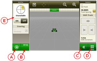 John Deere 4100 CommandCenter
 A. Next run page
B. Status center
C. Expand shortcut keys
D. Menu
E. Run page
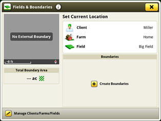
CommandCenter boundaries
Generation 4 is capable of importing existing boundary information from GS3 2630 or John Deere Operations Center. Gen 4 is also capable of creating boundaries from coverage.
The display uses a streamlined boundary creation process that generates exterior and interior field boundaries from coverage, simplifying the process and reducing steps. Operators can delete interior boundaries without impacting the exterior boundary or headlands. In addition, operators can chose to turn boundaries off for Section Control, while using them for field locator and documentation.
Headland boundaries can also quickly be generated by simply entering a distance or the number of passes from exterior boundary.
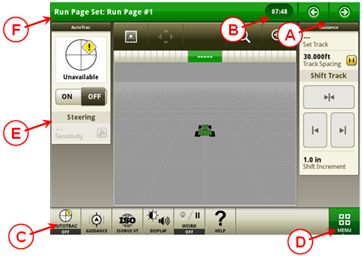 John Deere 4600 CommandCenter
 A. Next and previous run page
B. Status center
C. Shortcut keys
D. Menu
E. Run page
F. Title bar
Generation 4 CommandCenter and GreenStar displays comparison and compatibility
Generation 4 CommandCenter Display works in dual display mode with GreenStar (GS) 3 2630 Display, GS2 1800 Display, and GS2 2600 Display. For complete feature comparison and dual display compatibility information, please see the display comparison chart and GS3 and AMS display compatibility chart.
 Boundary creation from coverage
 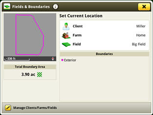 Boundary creation from coverage
 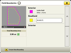 Headland creation
 Boundaries can be imported from the following sources:
- John Deere Operations Center
- Directly from a GS3 2630 Display or another Gen 4 CommandCenter
- Apex™ software or another farm management information system (FMIS) system that exports in GS3 2630 Display format
Hydraulic pump options to meet varying flow requirements
All 8R and 8RT Series Tractors come standard with an 85-cc displacement integrated hydraulic pump. This pump provides 227.1 L/min (60 gpm) of hydraulic flow.
A dual-pump option, featuring 85-cc and 35-cc displacement hydraulic pumps, is available for all 8R wheel models. The dual-pump system provides a hydraulic flow of 321 L/min (85 gpm), ideal for running at lower engine speeds.
SCV flow (approximate) | ||
Engine rpm | Pump flow (85-cm3 pump) L/min (gpm) | High pump flow (85-cm3 pump + 35-cm3 optional pump) L/min (gpm) |
800 | 86 (23) | 122 (32) |
1500 | 162 (43) | 229 (61) |
1700 | 184 (49) | 260 (69) |
1900 | 206 (54) | 290 (77) |
2100 | 227 (60) | 321 (85) |
Operating the tractor at reduced engine rpm contributes to a quieter cab, reduced fuel usage, and maintains the vacuum while turning and raising the planter on end rows. At 1500 erpm with a 321 L/min (85 gpm) system there will be an available flow of 229 L/min (61 gpm). This is an improvement over an available 162 L/min (43-gpm) flow when operating with a 227 L/min (60 gpm) system at 1500 erpm.
The maximum flow through one selective control valve (SCV) with a standard coupler is 132 L/min (35 gpm). A 19.1-mm (3/4-in.) high-flow coupler allows for a maximum flow rate out of one SCV of 153 L/min (40.5 gpm).
The hydraulic system is a closed-center, power-on-demand system using a load-sensing pressure-flow compensated axial piston pump with full-flow charge and flow prioritization for steering and brakes.
The pump outlet pressure available on demand can range from 3000 kPa (435 psi) for track models and 4000 kPa (580 psi) for wheel models at low standby to 20,400 kPa (2958 psi) at high standby.
Hydraulic pump options:
- 85-cc displacement, 227-L/min (60-gpm) hydraulic pump
- NOTE: Standard on all 8R models.
- 85-cc and 35-cc dual pump option, 321-L/min (85-gpm)
- NOTE: Compatible with 2014 Final Tier 4 (FT4) and newer 8R Wheel Tractors only.
Hydraulically actuated, power wet-disc brakes
The brakes are designed with large-diameter rear disc brakes and powerful activating pistons. The brakes run in oil for cooling and long life in the most demanding situations. Braking in the field during a turn can be accomplished with light pedal effort and excellent modulation of brake forces.
Hydraulically actuated, power wet-disc brakes:
- Never require adjustment
- Oil cooled for long life
- Tractors equipped with front brakes use annular pistons that automatically retract after each braking operation to reduce friction for better fuel economy
- Self-equalizing feature ensures even braking to each wheel
- Integrated backup braking capabilities built into the brake system to provide positive brake engagement should the engine or hydraulic system fail
- Brake valve is located externally of the cab to provide a quiet operating environment
An integrated park brake is included with all transmission options.
Front wet-disc brakes are included on 8R Series Tractors equipped with the 50-km/h (31-mph Independent-Link Suspension (ILS™) axle and 7R Series Tractors equipped with a 50-km/h (31-mph) Triple-Link Suspension (TLS™) Plus front axle. Front Brakes are optional equipment on the 8R 42-km/h (26-mph) ILS axle and 40-km/h (25-mph) TLS Plus front axles.
Foot brakes on tractors equipped with AutoPowr™/Infinitely Variable Transmission (IVT™) transmissions have an integrated AutoClutch™, as described in the IVT section. Similarly, foot brakes on tractors equipped with e23™ transmissions have integrated AutoClutch™, as described in the e23 section.
For towing very large loads, the 7R and 8R Series Tractors can be equipped with a complete air-brake-system or a hydraulic brake coupler, or both. The brakes supply air or oil pressure to a brake-equipped trailer or implement.
Cooled exhaust gas recirculation (EGR)
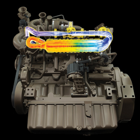 PowerTech™ PSX 9.0-L engine
 How exhaust gas recirculation (EGR) works
EGR reduces the high temperatures where nitrogen oxide (NOx) compounds are formed in the engine cylinders by replacing excess oxygen with a prescribed amount of cooled exhaust gas.
Exhaust gases contain more carbon dioxide than oxygen. The EGR valve in conjunction with the venturi and engine control unit (ECU) allows a controlled amount of exhaust gas to enter the intake manifold to mix with the incoming fresh air. Replacing excess oxygen with cooled exhaust gas leads to lower combustion temperatures, creating less NOx. In addition, EGR allows for advanced timing, leading to optimal performance of the engine, maximizing fuel economy.
The following diagrams illustrate how air flows through the engine.
For added performance and efficiency, the engine passes the exhaust gases through an EGR cooler before it enters the engine.
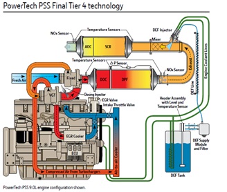 PSS engine diagram
 Flow of exhaust during engine operation
Exhaust airflow enters into the EGR cooler from the exhaust manifold near the turbocharger.
Based on engine load, air temperatures, and rpm, the engine control unit (ECU) opens or closes the EGR valve, allowing a measured percentage of exhaust gas to enter the intake manifold.
The gases mix with the rest of the incoming air from the turbocharger and aftercooler before entering the cylinders.
Lighting packages provide 360 degrees of coverage for maximum productivity
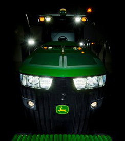 Premium lights
 The 7R, 8R, and 8RT Series Tractors feature two lighting package options:
- Standard
- Premium
The cab lighting pattern provides 330 degrees of coverage while the hood lighting provides the remaining 30 degrees for completely programmable 360-degree, stadium-style lighting. This ensures there are no dead zones or lighting adjustments needed. The lighting configurations are available to match various applications and ensure maximum around-the-clock productivity.
Bulb housings are large, allowing for optimum total lumens and available light. The standard lighting packages use 65-W halogen bulbs, whereas the premium lighting package uses light-emitting diode (LED) lights. In the premium lighting package, these tractors take advantage of the high-performing and efficient LED technology.
The low- and high-beam driving/work lights are adjustable. Please refer to the electrical section in the operator’s manual for complete details on adjusting lights.
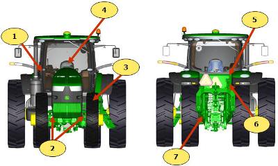
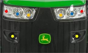 7R/8R/8RT lighting
 Yellow circles
- All lighting packages: 65-W halogen: road low beam
Red circles
- Standard: 65-W halogen
- Premium: LED
Blue circles
- Standard: 65-W halogen; field and road high beams
- Premium: LED
Orange circles
- Standard: blank
- Premium: LED
|


Standard lighting
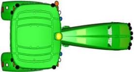 Standard lighting (8R)
 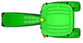 Standard lighting (7R)
 Six front grill-mounted lights:
- Two 65-W low-beam driving/work lights (mid grill screen)
- Two 65-W high-beam driving/work lights (top of grill screen, hood mounted)
- Two front corner-facing halogen work lights (top of grill screen, hood mounted)
10 cab roof-mounted lights:
- Two rear-facing 65-W floodlights
- Four side-facing 65-W floodlights
- Four corner-facing amber lights
Other lights:
- Two rear fender-mounted floodlights
- Two rear turn signal and brake/tail lights (fender mounted)
- Two folding-extremity lights
Plus these lights:
- Two adjustable front roof 65-W halogen floodlights
- Two front belt-line floodlights
- Rotary beacon light
Selecting a lighting mode/programmable lighting
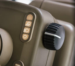 Lighting mode selector
 Operators can quickly select a lighting mode on the steering console:
- Lights, off position
- Road lights
- Field lights
 The CommandCenter™ display
 The CommandCenter display allows operators to customize light settings. Operators can select only the lights they need or want for a given application and store these settings. The operator-programmed configurations can then be turned on or off with the push of a button on the CommandARM™ controls.
- Programmable field lights 1
- Programmable field lights 2
- Beacon light
- Emergency flashers
NOTE: Road/loader lights are also referred to as high-mounted driving lights for use in front hitch applications that obscure the headlights. See the Attachments section.
The battery power saver feature is also standard. When the engine is off and the outside lights have been left on, this feature is designed to avoid battery run down.
After the lights have been left on for 30 minutes and the key is in the off position, the lights cycle or blink on and off five times as an alert. The lights continue to illuminate for one more minute and then automatically shut off to protect the battery.
Field-installed options
Field-installed options are also available. To find this information, use the Build Your own Configurator application for US/Canada or Build & Price in John Deere Sales Centre for Australia/NZ.
Premium lighting
Eight front grill-mounted lights:
- Two 65-W low-beam halogen driving/work lights (mid grill screen)
- Two LED high-beam driving/work lights (top of grill screen, hood mounted)
- Two front corner-facing LED work lights (top of grill screen, hood mounted)
- Two front-facing LED working lights (top of grill screen, hood mounted, inner position on the sides)
12 cab roof-mounted lights:
- Four side-facing LED lights
- Four corner-facing amber lights
- Two rear-facing LED lights
- Two adjustable front roof LED lights
Other lights:
- Two rear fender-mounted LED lights
- Two rear turn signal and brake lights (fender mounted)
- Two folding-extremity lights
- Two front belt-line LED floodlights
- Rotary beacon light
The premium lighting package replaces all previous halogen and HID lights with LED lights. The only lights that are not LED are the low-beam driving lights, they remain halogen. This allows each LED light to work at a lower temperature and no one light works harder than any other. The uniformity in LED coverage allows only one type of light output surrounding the tractor.
The lighting pattern in the premium package provides industry-leading performance in nighttime visibility. LED bulbs provide maximum brightness and a true color output for excellent field definition that is easy on the operator's eyes.
The LED lights provide 40 percent greater coverage width and 10 percent more light coverage in the rear. LED lighting packages use 45 percent less amps than standard halogen lights and have an increased life expectancy over HID lights which leads to lower costs of ownership over the life of the tractor.
NOTE: Lighting packages may vary depending on region.
Programmable exit lighting
Another feature is programmable exit lighting. Exit lighting allows the lights outside the cab to stay on for up to 300 seconds. They can be programmed in increments from 0 to 300 seconds.
Refer to the operator’s manual for complete instructions on programming field, driving, and exit lighting.
| Option code | Description |
| 7201 | Standard lighting |
| 7206 | Premium lighting |
Gold Key Program Waterloo operations


The John Deere Waterloo Operations Gold Key Program was designed to recognize and honor those purchasing Waterloo-built tractors. The Gold Key tour provides an opportunity for a customer to follow his or her tractor as it is built on the assembly line. If a Gold Key customer is unable to visit the day the tractor is on the assembly line, the customer may elect an alternative date within 90 days to schedule a tour. This will be recognized as a Gold Key experience where the customer adopts a tractor to follow rather than watch his or her own tractor being built. After 90 days, the visit will be deemed a VIP tour and Gold Key memorabilia will not be provided.
Definition of a Gold Key tour
A Gold Key tour entails an exclusive, behind-the-scenes guided tour of the assembly production lines. The customer, or product owner, may bring up to three additional guests on the tour. Tour participants will wear Gold Key owner identification bump caps and other personal protective equipment while being escorted privately by a tour guide. Every attempt will be made to make sure the customer will see the specific tractor ordered come off the final assembly line; however, in order to satisfy delivery needs, the first priority is to keep the manufacturing lines running at full capacity.
The Gold Key visit date is based on when the customer’s tractor is expected to reach the final line. It is John Deere’s goal that a customer drives his or her tractor off the final line at the end of the tour. It is imperative to notify the John Deere dealer from whom the tractor was purchased in order to initiate a Gold Key tour. The John Deere dealer will be required to register guests on the Gold Key registration website as soon as possible if a Gold Key visit is requested. The owner will be presented with a gold key, a certificate, and other memorabilia at the conclusion of the factory visit. Breakfast and lunch will also be provided the day of the tourisit.
Process of Gold Key tour
The owner will need to notify the John Deere dealer where the Waterloo-built 6000 Series – 9000 Series Tractor was purchased. The Gold Key coordinator will be the sole contact with the dealership representative to make visit arrangements and confirmations for the visit.
Shortly after the Gold Key coordinator confirms the request, all appropriate paperwork and information will be sent to the dealer. The customer will then receive all welcome documents in the mail. The Gold Key coordinator will also make direct contact with the customer to confirm the visit.
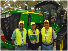 Ahrens Farms
Ahrens Farms of Owatonna, MN participated in the Gold Key Tour at John Deere Waterloo Works in 2015. They purchased a 9470RT Tractor.
Gold Key Tour guidelines
- All Gold Key tours must be initiated by the selling John Deere dealer through the Gold Key profile request form.
- The Gold Key coordinator at the Waterloo Tractor Factory will be responsible for updating the customer and dealer of the tractor build status.
- Gold Key treatment will not be recognized if any of the requirements are not met prior to arrival at the factory.
- The Gold Key Program is only available within 90 days of the tractor's build date.
- Every attempt will be made to make sure the customer will see his or her tractor come off the assembly line; however, the factory has first priority for production obligations.
- Gold Key tours are limited to the customer and three other persons, no more than four people total (excluding dealer).
- All guests attending Gold Key tours must be 13 years of age or older. Any teenage children must be accompanied and under constant supervision of a parent and/or guardian.
- No personal cameras or video cameras are allowed on the production floor during the tour. A camera from John Deere will be given to Gold Key guests for the duration of the tour.
- Tour participants must abide by all factory tour safety rules and regulations.
- Gold Key tours will be restricted if maximum tour capacity has been reached due to previously scheduled tours or special events.
While every attempt will be made, and the factory will do everything possible to allow a customer to see his or her tractor being built, production schedules change for many reasons. Should production change at the last minute, the owner may arrive only to find that either the tractor has been pushed back or pulled ahead and already built. While that is certainly not the intention, the possibility remains.
The factory cannot be responsible for:
- Production delays, work ahead, or production revisions
- Any option changes at the factory level
- Overnight accommodations; however, assistance with information is available upon request
- Travel costs
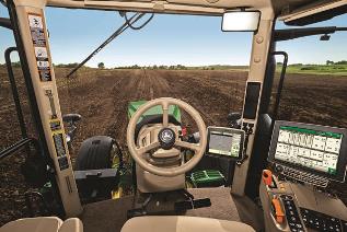
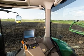
Standard CommandView™ III cab offers unsurpassed amenities
 CommandView III cab
 The Standard CommandView III cab offers unsurpassed visibility, operator comfort, control placement, and ride and sound quality.
Features:
- ComfortCommand™ seat with air suspension, lumbar support, swivel, fore-aft and lateral attenuation, backrest angle adjustment, adjustable left-hand armrest, and 40-degree right-hand seat swivel
- Operator presence system that warns if the operator is out of the seat while operating key functions
- Folding instructional seat
- CommandARM™ console with integrated controls
- 4100 or 4600 Generation 4 CommandCenter™display
- Behind-the-seat storage
- Left-hand storage compartment
- Passive noise reduction system
- Service ADVISOR™ data port
- Tilt/telescoping steering wheel with position memory
- Swing-out rear window, opens 30 degrees
- Right- and left-outside mirrors (manually adjustable mirror head)
- Monitor mounts on right-hand front post and rear cab post
- Standard radio package, including AM/FM stereo and weatherband with remote controls, auxiliary input jack, four speakers, and an external antenna
- Laminated glass
- Air conditioner and heater with automatic temperature controls (ATC)
- Two 12-V convenience outlet (cigarette lighter style)
- One 12-V 3-pin outlet with adapter (provides switched and unswitched power)
- One International Organization for Standardization (ISO) 9-pin connector
- Power strip with convenience plug adapter
- Hitch control lever lock and selective control lever lock
- Two-speed and intermittent front and rear wiper with washer
- Front pull-down sunshade
- Digital cornerpost display with:
- Fuel level gauge, including low fuel warning
- Temperature gauge
- Diesel exhaust fluid (DEF) gauge, including low DEF warning
- Engine rpm
- Transmission commanded gear or speed
- Vehicle system functions, such as iTEC™ system, that are operating
- Inside-mounted rearview mirror
- Beverage holders sized to accommodate various containers
- Interior left-hand dome light
ComfortCommand seat
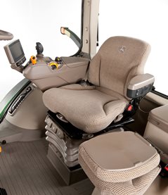 ComfortCommand seat
 ComfortCommand seat improves ride quality and helps to reduce operator fatigue
Features include:
- Armrests, lumbar support, and backrest angle are easily adjusted to match operator preference.
- Shock absorbers dampen the motion effect of the tractor for an improved ride.
- Seat height adjustments are conveniently located on the left armrest.
- Fore-aft adjustment is easy to reach located on the left front of the seat.
- Swivel adjustment, located on the front of the seat, allows the seat to be swiveled 40 degrees to the right or eight degrees to the left of the center position.
- Operator presence switch warns if the operator is out of the seat while operating key functions.
- Seat belt retractor.
- Centered cab seat, providing excellent over-shoulder visibility.
- Adjustable shock absorber permitting ride adjustment from soft to firm to match the operator's desired comfort level.
- Removable cushions for easy cleaning.
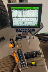
CommandARM
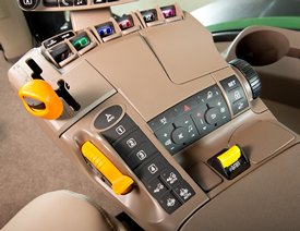 CommandARM controls
John Deere 7R and 8R Series Tractors feature the CommandARM with integrated Generation 4 CommandCenter display. The control layout of the CommandARM utilizes a clean and efficient design which groups controls by function and builds upon John Deere’s history of intuitive and ergonomic control placement and operation. The CommandARM’s design allows for a 40 degree right seat swivel and adjustable positioning matching the operator’s preference.
Controls located on the CommandARM include:
- Engine throttle
- FieldCruise™ system
- Minimum engine speed – CommandQuad™ transmission, 16-speed PowerShift™ transmission (PST), e23™ transmission
- Eco mode – Infinitely Variable Transmission (IVT™)
- Foot pedal lock (if equipped)
- Transmission control
- Hitch/selective control valve (SCV) controls
- Rotary encoder hitch control
- Power take-off (PTO) controls
- Mechanical front-wheel drive (MFWD) on/automatic
- Differential lock on/automatic
- iTEC sequence switches
- AutoTrac™ assisted steering system resume switch (if equipped)
- Joystick (if equipped)
- Radio
- Beacon light on/off
- Hazard lights on/off
- Field lights 1/2
- Heating, ventilation, air conditioning (HVAC) system
Transmission controls
John Deere 7R Series Tractors with CommandQuad transmissions feature a left-hand reverser. 8R Series Tractors equipped with 16-speed PST are equipped with right-hand reverser. 7R Series Tractors equipped with e23 PST offer a left- or right-hand reverser. 7R or 8R Series Tractors equipped with AutoPowr™/IVT transmissions are offered with either a left-hand or a right-hand reverser.
The transmission control lever is placed on the CommandARM’s left side closest to the operator for convenient setting and adjustment.
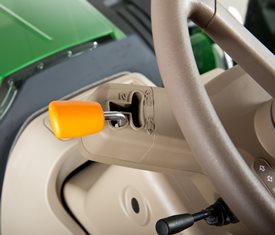 Left-hand CommandQuad/e23 reverser
 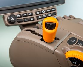 Right-hand IVT and PST reverser
 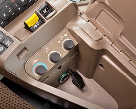 Hitch controls
 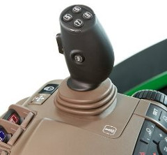 Optional crossgate joystick
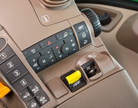
 Throttle
The throttle design incorporates buttons which control FieldCruise speed, foot pedal mode (if equipped), and transmission eco settings.
 16-speed PST right-hand reverser
 Hydraulic and hitch controls
Hydraulic and hitch controls utilize fingertip paddle pots for raise/lower and extend/retract functions. An optional crossgate joystick replaces fingertip paddle pots for control of SCVs and allows for programmable hydraulic functionality according to operator preference. Rear hitch position can also be controlled with the encoder wheel located on the right side of the CommandARM. The encoder wheel allows for finite positioning of the rear 3-point hitch.
Three buttons near the encoder are for hitch set, lock, and return to height. Adjustment knobs for the 3-point hitch are located under the cover for the CommandARM’s storage compartment and allow for adjustment of the rate of drop, hitch height limit, and depth control.
 Fingertip paddle pots
 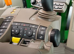 Encoder wheel
 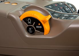 Throttle
 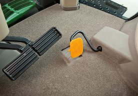 Foot throttle
 Tractor function controls
Located just to the right of the throttle is the Auto-Trac activation button and four sequence controls for iTEC functions. Behind the iTEC sequence controls, there are buttons which control the activation and deactivation of MFWD and differential lock. Differential lock can also be activated by the foot switch on the cab floor.
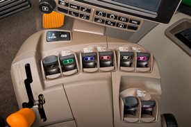
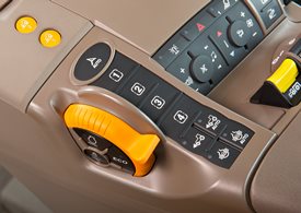 AutoTrac resume and iTEC strip
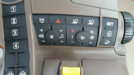
 Controls for radio, lights, rotary beacon (if equipped), hazard flashers, and HVAC system are located to the center-right on the CommandARM, along with PTO for both front (if equipped) and rear PTO.
 Radio, HVAC, hazard flashers, and PTO controls
 Seat swivel
The design of the CommandARM allows for up to 40 degrees of right-hand seat swivel.
 Seat swivel
 CommandCenter
 Generation 4 CommandCenter
 The Generation 4 CommandCenters feature fast adjustment of tractor functions and controls and are integrated into the CommandARM to create a seamless control center. The 4100 CommandCenter features a 178-mm (7-in.) touchscreen display and is standard equipment on 7210R and 7230R models, while the 4600 CommandCenter features a 154-mm (10-in.) touchscreen and is standard equipment on 7250R – 7310R models, as well as all 8R and 8RT models.
The following functions can be adjusted using the CommandCenter display:
- Hydraulic settings
- Hitch settings
- Transmission settings
- FieldCruise
- iTEC programming functions
- Radio
- Lights
ActiveCommand steering (ACS™) provides a robust and full-encompassing steering system
ACS overview
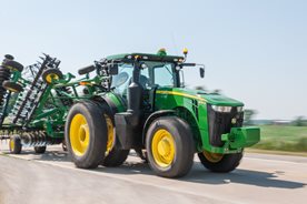 8R in transport
 With ACS, John Deere has designed one of the most robust and full-encompassing steering system in the industry. Whether in the field or on the road, ACS reduces steering effort, which can result in reduced operator fatigue and can improve operator comfort.
There are four key features of the ACS system:
Dynamic road wheel offset:
- A gyroscope senses tractor yaw and can automatically make small steering adjustments to provide unprecedented line-holding abilities. Drive down a bumpy road and experience how ACS makes it easier to keep the tractor straight, even over rough terrain. ACS delivers the ultimate in comfort.
- ACS works to prevent over-steering when a sudden obstacle causes the operator to make a quick steering reaction.
Variable ratio steering:
- Approximately 3.5 turns lock-to-lock at in-field speeds for quick headland turns.
- Approximately 5 turns lock-to-lock at transport speeds.
Elimination of steering slop and hand wheel drift:
- Steering wheel drift and slop are eliminated with the ACS electronic control system.
Variable effort steering:
- Steering wheel resistance automatically changes with ground speed to deliver light steering effort at slower speeds for less effort during headland turns, and higher steering wheel torque at transport speeds for better comfort.
A fail operational system
The ACS system is fail operational, which means steering is still functional in the event of any single-point failure. John Deere has gone to great lengths to help ensure the operator has the ability to steer the tractor if something goes wrong in the steering system.
For example, if the primary controller fails, a second controller takes over. If power from the alternator fails, the battery resumes control. If the engine quits running and is unable to supply hydraulic oil to the system, an electric-driven backup pump is used to supply the oil. There is a backup for ACS components.
 ACS components
 The ACS system consists of several key components:
- Gyroscope: this is used to measure the yaw rate (turn rate) of the tractor during transport speeds.
- Road-wheel angle sensors: these sensors simply measure the steer angle of the tractor.
- Power supply module: this module distributes the power of the battery and alternator throughout the ACS system.
- Hand-wheel angle sensors and tactile feedback unit: this includes the steering wheel position sensors and a brake which can increase or decrease resistance dependent on speed. Lighter feedback is desired during normal field use, and slightly heavier feedback is desired during transport and while the tractor is cornering at high speeds.
- Controllers: two controllers are located in the back of the tractor and are the brains of the system.
- Control valves: also known as steering valves, control valves are used to steer the tractor.
- Electric-drive backup pump: this pump supplies oil to the steering system, brakes, and park (for towing) brake if there is no longer a sufficient oil supply to the steering and brakes.
Value of ACS
- Improves line holding when driving at transport speeds
- Fewer turns lock-to-lock: 3.5 turns lock-to-lock in the field for quicker headland turns and 5 turns lock-to-lock at transport speeds
- Eliminates hand wheel backlash and drift
- Reduces steering effort results in reduced operator fatigue
- Smaller hand-wheel diameter for improved operator comfort and visibility
- Maintains operator feel and touch-points of traditional steering column system
- Fully integrates with AutoTrac™ guidance assisted steering stems
- Compatible with suspended and non-suspended front axles
- Compatible with wide and narrow section width tires