
H240
Loader
- Enhanced strength and durability
- Perfect tractor stability
- High capacity hydraulics
- Unmatched visibility
Features
A loader built for performance and durability
One outstanding boom designed with selected and tested components
 Integrated hose design
  Calculated and tested design
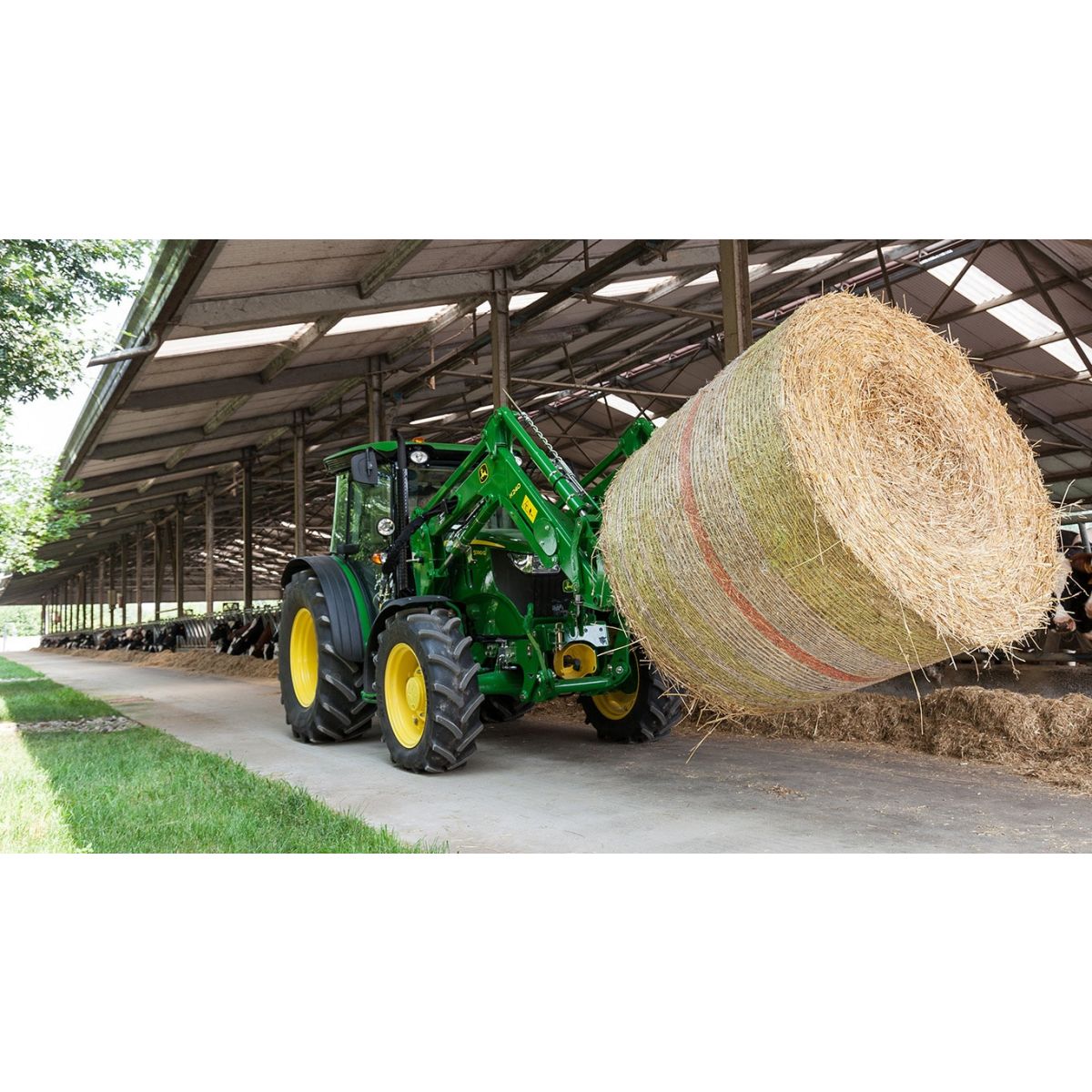
 The H-Series Front Loaders are the best partner for John Deere tractors. The boom is specially designed to optimize visibility with a wide dimension and integrated hydraulic hoses. The durability of the loader, which uses tested components, ensures the tractor will operate at maximum efficiency when used with the front loader.
Visibility and durability are important for the operator, but so is control. To ensure control of the loader attachments, H-Series Loaders are equipped with an exclusive bucket-level indicator, which indicates the angle the attachment is situated.
More visibility
 Clear visibility
 Designed with a torque tube in a low position, the H-Series Loaders provide the operator good visibility of the attachment no matter what lift height the loader is placed. The low position of the torque tube also allows clearance for the tractor’s front lights, which provides an ideal lighting solution for nighttime use.
Hydraulic integration
 H260 front loader with the torque tube cover design
 The integration of the hydraulic components also provides good operator visibility because everything is located inside the boom.
With the concealed oil lines, visibility is improved and the components are protected such as hoses, suspension, the diverter valve, and the relief valve. The ability to take the cover off the torque tube allows operators to access to the complete hydraulic package, which enables working on the hydraulic parts to be completed in a limited time.
Hydraulic components located around the torque tube
 Torque tube components
| Number | Description |
| Suspension |
| Relief and diverter valve |
| Third function |


The H-Series Front Loader is a premium product with concealed hydraulic oil lines. The suspension (1) location is well protected inside the torque tube and can be easily taken out with quick connectors. To activate and deactivate the suspension, an electro vane is connected to the gas accumulator. The diverter valve (2) and the directly-connected relief valve are located above the torque tube, but still protected under a removable cover. These valves are located on the other side of the third function (3). th the directly connected relief valve (2a) and on the other side the 3rd function (3). The quick unlatch (not pictured) is located right next to the diverter valve (2). The torque tube cover is screwed on a metallic skeleton and can be easily taken off with just a wrench.
Specific parts for outstanding durability
 Front loader on the test bench
  Cast-steel parts in orange color
 To achieve a stronger durability level, all pivot points were redesigned with a wider contact surface and are made from cast-steel material. These improvements decrease the pin´s wear and support the heavy-duty applications. Finally, the H-Series Loaders feature specific pins equipped with a grease nipple in all pivot points. They are designed for a long lifetime and do not require replaceable bushings.
Suspension inside the torque tube
 Suspension activation
  Suspension button inserted in the right-hand console when retro-fitted
 The suspension button is integrated on the joystick (1). To activate and deactivate the suspension, the gas accumulator is connected to an electro vane. The suspension is connected to the lift cylinders, which move in and out to allow the boom to float, and thus provide a comfortable drive-in addition to protecting the material handled. A field-installed bundle can be ordered; a separated button will be delivered with the kit.
False-rod cylinders
 False-rod bucket cylinder
 In order to be as productive as possible, fast bucket cycle times are important to dump the load from the bucket quickly. The bucket cylinder design can have a major impact on this cycle time, especially for the mechanical self-leveling (MSL) loaders.
All MSL H-Series Loaders use false-rod bucket cylinders. A false-rod cylinder has a smaller displacement of oil requirement on the head end of the cylinder, which allows this cylinder to dump much faster than a normal cylinder.
Safety feature
 Shut-off valve open
  Shut-off valve closed
 A hydraulic shut-off valve is included in base with the H-Series Ag Loaders to ensure the loader does not lower suddenly. This allows the boom to be locked-out when someone is required to be located under the loader boom, for example, during service work on the tractor.
Parking lock for Australia
 Parking lock used for serviceability work on tractor
  Parking lock storage solution
 In addition to the shut-off valve, a parking lock, located on both lifting cylinders, is mandatory for use in Australia. The parking lock blocks the cylinder and thus prevents the front loader to lower when working under the front loader to conduct maintenance or serviceability work on the tractor for example. The front loader is equipped with this parking lock in base when ordering for Australia.
Easy to maintain
 Greasing points integrated in the design pivot pin
 The grease nipples are protected by the specific cast-steel parts design. This allows quick and easy access, without having to remove anything. The pivot pins have an eccentric design which makes sure that it will not rotate during loader movements, and it also keeps the grease in the pivot surfaces. This non-rotation of the pin is an important point to avoid any pin deformation and un-regular wear of the parts.
Easy to mount and dismount the loader
Only three quick steps are required to safely disconnect the front loader
 Step 1
 Place the loader on the ground with the bucket dumped.
 Step 2
 Put the parking stand down.
 Step 3
 Remove the mast pins.
After this step, the tractor can be brought in neutral position and the front loader removed with the help of the bucket and lift cylinders. Once the front loader masts are disconnected from the mounting frames, the next step can be conducted.
Before taking the multicoupler off, release the pressure of the hydraulic hoses by moving the joystick in all directions. Then take the multicoupler off and place it on the front loader boom as shown.
Reverse the tractor and continue your work.
The first step is to put the front loader down and dump the bucket to release the weight of the loader on the tractor. The second step is to place the parking stand down and remove the mast pins. Rotate the mast forward by extending the lift cylinder until it has rotated past the pin location on the mounting frame. Now, using the bucket circuit, roll back the bucket until the mast is removed from the mounting frames and will clear the tires. This manipulation can be done with the tractor in the neutral gearbox position. With the tractor in park, the third step is to shut off the engine and relieve the hydraulic pressure as indicated for the tractor, and then disconnect or open the single-point hydraulic connector.
Tractor-ready feature saves time and ensures quality integration with front loader
Tractor ready for front loader, available directly from the factory
 Tractor ready for 5M-compatible front loader
  Tractor-ready front loader
 The tractor-ready feature is an option orderable from the factory for the 5M and 5G Series Tractors. This option allows dealers to receive the tractor equipped with the loader components directly from the tractor factory. The tractors are then delivered with the mounting frames, the mid-mount valve with hoses, and hydraulic fittings, the mechanical joystick, and the loader coupling points, mounted and tested.
The loader-ready option is also available for the3-cylinder 5E Tractors Stage IIIA (Tier 3). Please find more information in the product announcement.
 5E with loader- ready parts
The loader parts which are installed on the tractor are:
- Mechanical joystick for 5E, 5G, and 5M (additionally, electronic joystick available for 5G)
- Tractor valve and tractor hydraulics
- Hydraulic connection between tractor valve and loader coupling system
- Loader coupling system (multicoupler for 5M and 5G; four individual couplers for 5E)
- Hood guard
- Mounting frames
The 5M and the 5E tractors have a mid-mounted valve; the 5G has the valve mounted on the rear of the tractor. Other than that, there are no differences between the front loader-ready packages of the tractors
 Tractor-ready 5M-compatible front loader with hood guard and toolbox
 In addition to the operational parts, a toolbox and one hood guard are provided. This means that in less than 15 minutes, the tractor can directly receive the front loader.
Mounting frames design
 Mounting frames installed on tractor frames
  Mounting frames
  Mounting frames with integrated toolbox
 The mounting frame is designed with a special shape to optimize fender and wheel clearance, ensuring easy access to the tractor engine for service operations. The durability has been tested to ensure the loader can withstand heavy-duty applications. Additional holes on the mounting frame allow the assembly of the toolbox and the multicoupler bracket.
Valve integration
 Valve integration under 5M Tractor cab
 The valve integration of the different tractors under or behind the tractor cab provides protection and a good connection from the valve to the joystick, as well as from the valve to the multicoupler. This short distance provides the operator with maximum accuracy through limited effort by using the mechanical joystick.
Joystick installation
Joystick lever control connection (5M shown)  Joystick lever control integration (5M shown)
 The mechanical joystick is installed at the factory; the integration is ideal for those seeking easy access, simple use, and a convenient ergonomic location. The operator can have ideal control of the loader and keep the handling operation as efficient as possible.
3-cylinder 5E Stage IIIA Tractor shown | 5G Stage III A Tractor shown | 5M and 5R Stage III A Tractor shown | 5M and 5R Tractor with front hitch Stage IIIA |
|
|
|
|
3-cylinder 5E Stage IIIB Tractor shown | 5G Stage III B Tractor shown | 5M Stage IIIB Tractor shown | 6D Tractor shown |
|
|
|
|


Tractor hood guards
The design of the hood guard is well chosen to protect the hood of the tractor and the lights from damage, but still enables easy access to the parts underneath the hood to perform service or maintenance work.