

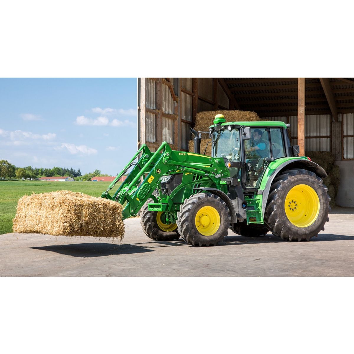
623R
Loader
- Mechanical Self-Levelling (MSL) and Non Self-Levelling (NSL*) options
- Unobstructed view
- Safe, easy mounting
- Effortless locking
Features
Connect/disconnect the loader faster with the new Automatic Mast Latch
Only leave the cab once to disconnect the loader
It takes four steps to disconnect the loader: lower the loader, open the parking stand, remove the hydraulics, and unlock the mast pin.
 Loader placed on the ground with the bucket leveled (1)
  Open the parking stands (2)
  Unlock the hydraulic (3)
  Unlock the loader mast (4)
 To disconnect the loader, the bucket has to be flat on a stable ground (1). The operator has to leave the cab and lower the self-adjustable parking stands on both sides of the loader (2): the self-adjustable parking stands allow the driver to park the loader on irregular terrain and still keep a good position relative to the mounting frame, to attach the loader correctly later on .The parking stands can be set without tools.
After lowering the parking stands, the hydraulic couplers on the right-hand side of the loader have to be removed (3) and the loader must be unlocked from the tractor mounting frames (4). After these four steps, the operator is ready to move the tractor (5 and 6).
 Leave the loader boom (5)
  Loader and tractor are disconnected (6)
 Fast connection of the loader to the tractor
 Store the parking stands (1)
  Connect the hydraulics (2)
 Connecting the loader is fast and convenient thanks to the ramp design on the mounting frames and the automatic mast latch equipped with a floating device. Only drive the tractor to bring the mounting frames inside the mast until the latching indicators are in lock position. Then the driver can lift up the parking stands (1) and connect the couplers (2) for hydraulic and electric loader power to the tractor. Fast, intuitive and maintenance free design, the loader connection and disconnection brings the tractor ready for any tasks.
Fast and easy implement latching/unlatching
Use the automatic implement latch to connect the loader implement faster
 Daily work: Connecting different implements
 Changing the implements is a daily task for many front loader operators. Thanks to the patented automatic implement latch (AIL) the connection of various buckets, forks, or other implements can be done in less than 3 seconds. The dedicated treatment and material choice ensure the rod supports the heaviest applications, which provides a durable and lifetime solution. The AIL is a base feature of the Euro carrier, which is compatible with all Euro implements. It is also available with the Combi Euro MX carrier.
Disconnect the implement
 Open the carrier handle (1)
  Remove the implement (2)
 To unlock the implement, the operator has to open the handle manually (1). Optionally, this is possible to do from the cab with the hydraulic implement unlatching (HIU). It requires minimal effort to unlock the implement, without the need of tools. The convenient position of the handle allows easy access for the operator. The operator needs to pull the handle and turn it clockwise. The handle will stay in the required position.
The next step is to remove the implement from the carrier (2): tilt the implement and lower the loader until the bucket touches the ground. The carrier rod is released from the implement hooks. The carrier handle moves to a standby position allowing fast latching later on.
Connect the implement
 Connect bucket with the carrier completely dumped
  Implement locking positions (1, 2) and the trigger of the AIL (2)
 The Automatic Implement Latch (AIL) locks the implement as soon as the implement lug touches the trigger plate on the carrier (2). To achieve this, the top bar of the carrier has to be connected to the implement’s top hooks and after start rolling back the carrier. But there is no need to completely roll back the attachment. The implement is latched on both sides of the carrier (1, 2). The fast and easy locking performs regardless of loader height.
Automatic Implement Latch (AIL) in details:
Position of the carrier handle during the latching process
- Position 1: Latch open – latch tube against carrier green plate
- Position 2: Latch tube against AIL plate
- Trigger waiting for implement lug
- Position 3: Latch closed
More comfort and visibility with the R-Series Loaders
Higher visibility with the R-Series
 New design
 The design of the R-Series Loaders increases the visibility of the implement at no matter what lift height the loader is placed. With its curved shape, the loader boom is aligned with the tractor hood and provides a better view when working with the loader. The position of the mechanical leveling link supports the higher visible level of the mechanical self-leveling (MSL). Due to the compact design of the boom and the cylinders, the raised distance of the cylinders to fenders guarantees sufficient clearance. This allows an appropriate steering angle to maneuver the loader in tight spaces.
The low position of the torque tube also allows good visibility and clearance for the tractor’s front lights, which provides an ideal lighting solution for night time use.
Loader lights
 Front loader lights increase the visibility
 Operating at dusk or night is a part of a producer’s working life. The increased visibility allows the operator to drive in a more comfortable and confident way. The loader lights are mounted on the loader boom and follow the loader movements. With 850 luminous flux per light, the light provides a powerful illumination to support working in dark conditions. The loader lights show a low power consumption of 15 watts per lights.
Comfort on the R-Series
Suspension
 Location of the loader suspension
  Loader suspension button on the mechanical joystick
 The loader suspension option further improves comfort when using the R-Series Loaders on uneven terrain. The gas accumulator is integrated and protected in the torque tube. The suspension is activated from the driver seat due to a button on the mechanical joystick (1) or a switch on the console with the electronic joystick. The loader suspension results in a smoother ride and less potential material loss.
Please go to loader suspension for more information.
Electronic self-leveling (ESL) packages
 View of the RTP display
 To make repetitive loader tasks easier and more accurate, John Deere now offers return-to- position (RTP) option which automatically returns the front loader to a preset position. The RTP is part of the ESL packages: the ESL standard package includes the non self-leveling (NSL) boom with RTP, whereas the ESL premium Package provides the mechanical self-leveling (MSL) boom equipped with RTP.
With RTP, the driver can save up to four implement positions: four implement heights and four implement angles. Due to the RTP, productivity can be significantly increased and provides an easy environment for the operator. This function removes the need to keep full concentration on the attachment position; the tractor can manage the loader thanks to a few clicks by the driver. For example, the driver can save four positions in a loading process. The operator loads manure: he takes up the manure (A), transports it to the trailer (B), lifts it above the trailer (C), dumps it into the trailer (D). He can return to all these positions by clicking the joystick in the appropriate direction. Due to the saved positions the risk of damages are minimized.
With the RTP option, there is no need to check the loader height and the implement angle when handling pallets, silage bales, wood, and gravel — the tractor takes the control. This means a complete loading cycle can be performed in 8 movements of the joystick. The electronic joystick and the intuitive CommandCenter™ controls further increases ease of usability.
Please go to the electronic self-leveling (ESL) packages for more information.
Gear Shift Switch (GSS)
 Mechanical joystick with GSS
 The gear shift switch (GSS) (1) on the joystick allows the operator to change the gears without moving the hand away from the joystick. During the loading process, different speed levels are required to operate quickly and efficiently. The GSS option is installed on the joystick. It is available for all loader models.
Please go to the GSS for more information.
Hydraulic implement unlatching (HIU)
 Gas accumulator to operate the HIU
 In base, all R-Series Loaders are equipped with a Euro carrier, which allows connection to all Euro implements to the loader, no matter which manufacturer provides the implement. The Euro carrier is delivered in base with an automatic implement latch (AIL).
The Euro and Combi Euro/Sms carrier can be equipped with the hydraulic implement unlatching option which greatly enhances the operator’s comfort, because it allows unlatching the implement by simply pressing a button from the operator’s station. There is no need for the operator to get out of the cab to remove the handle on the implement.
A gas accumulator is filled with oil when crowding the implement. To activate the device, the two switches installed in the right-hand side of the operator’s station are pressed simultaneously by the operator. This action releases the oil, and the implement is unlocked. Compared to competitors, it is still possible to unlock the implement manually.
Please go to the hydraulic implement unlatching for more information.
Rollback bundle
 Increased rollback angle
 With the rollback bundle, the operator can increases the rollback angle by 12 degrees and guarantees reduced material losses. Consequently, more material can be moved in one load which can help to reduce the number of loads and save time during loader operations. The implement parts have to be installed on the lower end of the bucket, where the implement is connected to the carrier frame.
Please go to the rollback bundle for more information.
Unmatched robustness and power of R-Series Loaders
Power
 John Deere R-Series Loaders are available with different types of leveling systems
 Due to the design and the loader kinematic, the R-Series Loaders feature outstanding power in regards to lift capacity and lift height. The power of the John Deere tractor is transferred to the loader via the hydraulic system.
The underslung leveling link of the mechanical self-loader (MSL) loader is connected to the false rod cylinders which results in fast cycle times (dumping and rolling back). The geometry allows a more rollback capacity which the operator can experience with stronger breakout forces. The compact boom has a lower height of pivoting points to easy access for greasing.
The detailed specification of the loaders can give an overview of the lift height and lift capacity of each loader (543R, 603R, 623R, 643R, 663R, and 683R).
Durability
 John Deere R-Series Loaders are built with a high level of durability
  Durability supported by torque tube
 The R-Series Loaders show a great level of durability due to the high-quality material. The modular cast-iron components on the loader are the foundation of a durable machine. The cast-iron mounting frames ensure a strong base for heavy-duty applications and guarantee a good connection to the tractor frame. This results in tested, reliable longevity.
The position and shape of the torque tube supports the heaviest loader applications and guarantees a stable behavior of the tractor and loader combination. Additionally, the compact boom design and the loader kinematics result in a strong and reliable solution the customer can experience in the field.
 Front loader on the test bench
  Cast-steel parts on the loader
 To ensure a high quality with outstanding durability, the R-Series Loaders have been tested on a dedicated front loader test bench, where the loader is subjected to heavy duty farming operations. All pivot points are designed with a wider contact surface and are made from cast-steel material. The pivot pins has a dedicated diameter and undergo a specific treatment to ensure an outstanding durability.
The welded, directional bushings have a specific shape to provide ideal stress distribution and support the heavy-duty applications.
Major pivot points are equipped with replaceable bushings for low frequency of greasing, because the grease continuously is delivered during the loader work. New bushings can be installed thanks to the specific bushing design.
 Position of pivot points on the loader
 Hydraulic integration
 Hydraulic lines are laid inside the boom
 With the John Deere loaders, the oil lines have been routed through the boom arm to protect them from any damage and to additionally increase the visibility of the driver. To provide good access to the hydraulics hoses, they are located on the top of the torque tube. The torque tube cover protecting the hydraulic components can be dismounted easily.
The loader suspension is located in the torque tube to protect the gas accumulator against external influences.
False rod cylinder
 False rod cylinder
 Fast bucket cycle times are important to dump the load from the bucket to be as productive as possible, while completing loading operations. The bucket cylinder design can have a major impact on the cycle time, especially for the mechanical self-leveling (MSL) loaders.
All MSL R-Series Loaders utilize false rod bucket cylinders. A false rod cylinder has a smaller displacement of oil requirement on the head end of the cylinder, which allows the cylinder to retract much faster than a normal cylinder.
Safety feature
 Shut-off valve open
  Shut-off valve closed
 A hydraulic shut-off valve is included in base with the R-Series Ag Loaders to ensure the loader does not lower suddenly. This allows the boom to be locked if someone is required to be located under the loader boom, for example, during service work on the tractor.
Easy loader removal using automatic mast latch
 Rear view of 600R Loader
 R-Series Loaders are even easier to attach and detach due to the automatic mast latch system. This feature provides efficiency to operations that require frequent loader parking. The automatic mast latch system is a mechanical lever that allows operators to remove or attach the loader with one trip out of the cab. The ease and convenience provided by the automatic mast latch system provides improvement to operation uptime.
 Automatic mast latch lever
  Visual lock/unlock indicator